I have created a volumetric mesh. I want to get the corresponding 2D projection coordinate (i.e. x, y positions) of each vertex coordinate on the DRR image projection plane.
I went through the GetDRRSiddonJacobsRayTracing Algirhtm [1], but it actually wants to input a 3D CT image volume and output the DRR image.
How can I obtain the (x, y) coordinate values in the DRR image plane for a given 3D coordinate position? For example, I have (x,y,z) positions for each vertex and I want to convert into (x,y) i.e. 2D projection coordinates on the DRR image plane? Can you please elaborate with an example ?
Apply transform point (e.g. here, here) to the appropriate transform. I don’t know whether direct or inverse transform should be used for your purpose.
I actually created a 3D CT image for each 3D volumetric mesh by voxelizing it using the vtk tool and then take the corresponding DRR image for each of these 3D CT image using the SidddonJacobRay tracing algorithm with gantry angle 0.
Now I want to get the corresponding 2D projection coordinate on the DRR image plane for each 3D vertex coordinate of the 3D mesh.
As you pointed out for example I have used the below code for only one 3D coordinate position in order to get the projection coordinates.
I need to clarify the below points.
How should I incorporate the gantry angle when taking these projection coordinates ? For that, is that ok if I use m_CamRotTransform as shown in the code below?
I assume that I do not need to worry about the source to isocenter distance when I’m applying this transformation right ?
One more thing to clarify, m_CamRotTransform->TransformPoint(point) actually outputs thee coordinates right (i.e. [x, y, z]) ? So in order to take (x, y) coordinate for the corresponding 3D vertex coordinate I should only use x, y values of the output of this method right (i.e. m_CamRotTransform->TransformPoint(point)) ?
Any python version of this itkSiddonJacobsRayCastInterpolateImageFunction is available ? How can I use the same functionality in python ?
From where can I find the initialization of m_Transform variable ? I’m not able to find the initialization of this variable in the code that you have pointed out? Please help this matter as well.
I just converted the aforementioned C++ code into python version to obtain the DRR projection for a given 3D vertex coordinate as you can see below. But unfortunately, Compose function outputs an wrong number of argument error (see below after the code block). Can you please help me on this matter to resolve this ?
Moreover, please let me know the correctness or if there is nay issues of the below implementation.
m_FocalPointToIsocenterDistance = 1000.; # Focal point to isocenter distance in mm.
m_ProjectionAngle = 0.;                  # Angle in radians betweeen projection central axis and reference axis
m_Threshold = 0.;

TransformType = itk.Euler3DTransform[itk.D]

m_Transform = TransformType.New()
m_Transform.SetComputeZYX(True)
m_Transform.SetIdentity()

m_InverseTransform = TransformType.New()
m_InverseTransform.SetComputeZYX(True)

m_ComposedTransform = TransformType.New()
m_ComposedTransform.SetComputeZYX(True)

m_GantryRotTransform = TransformType.New()
m_GantryRotTransform.SetComputeZYX(True)
m_GantryRotTransform.SetIdentity()

m_CamShiftTransform = TransformType.New()
m_CamShiftTransform.SetComputeZYX(True)
m_CamShiftTransform.SetIdentity()

m_CamRotTransform = TransformType.New()
m_CamRotTransform.SetComputeZYX(True)
m_CamRotTransform.SetIdentity()
# constant for converting degrees into radians
dtr = (math.atan(1.0) * 4.0) / 180.0
m_CamRotTransform.SetRotation(dtr * (-90.0), 0.0, 0.0)

m_ComposedTransform.SetIdentity()
m_ComposedTransform.Compose(m_Transform, 0)

isocenter = m_Transform.GetCenter()
# An Euler 3D transform is used to rotate the volume to simulate the roation of the linac gantry.
# The rotation is about z-axis. After the transform, a AP projection geometry (projecting
# towards positive y direction) is established.
m_GantryRotTransform.SetRotation(0.0, 0.0, -m_ProjectionAngle)
m_GantryRotTransform.SetCenter(isocenter)
m_ComposedTransform.Compose(m_GantryRotTransform, 0)

# An Euler 3D transfrom is used to shift the source to the origin.
focalpointtranslation = [None] * 3
focalpointtranslation[0] = -isocenter[0]
focalpointtranslation[1] = m_FocalPointToIsocenterDistance - isocenter[1]
focalpointtranslation[2] = -isocenter[2]

m_CamShiftTransform.SetTranslation(focalpointtranslation)
m_ComposedTransform.Compose(m_CamShiftTransform, 0)

# A Euler 3D transform is used to establish the standard negative z-axis projection geometry. (By
# default, the camera is situated at the origin, points down the negative z-axis, and has an up-
# vector of (0, 1, 0).)
m_ComposedTransform.Compose(m_CamRotTransform, 0)
# The overall inverse transform is computed. The inverse transform will be used by the interpolation
# procedure.

m_ComposedTransform.GetInverse(m_InverseTransform)

drrPixelWorld = m_InverseTransform.TransformPoint(point)
The error message in the console.
---------------------------------------------------------------------------
TypeError                                 Traceback (most recent call last)
<ipython-input-20-732777792e0b> in <module>
     31
     32 m_ComposedTransform.SetIdentity()
---> 33 m_ComposedTransform.Compose(m_Transform, 0)
     34
     35 isocenter = m_Transform.GetCenter()

TypeError: in method 'itkMatrixOffsetTransformBaseD33_Compose', argument 3 of type 'bool'
Additional information:
Wrong number or type of arguments for overloaded function 'itkMatrixOffsetTransformBaseD33_Compose'.
  Possible C/C++ prototypes are:
    itkMatrixOffsetTransformBaseD33::Compose(itkMatrixOffsetTransformBaseD33 const *,bool)
    itkMatrixOffsetTransformBaseD33::Compose(itkMatrixOffsetTransformBaseD33 const *)
You probably need to discard one of these 3 coordinates. I think it should be easier for you to figure out which one is depth, and which two are X and Y.
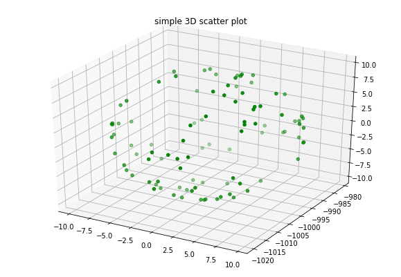
I have generated a list of random points in 3D space and got the DRR projection coordinates (i.e. x,y,z) using the aforementioned implementation. And then plotted them as you can see below and try to see they all line up the same plane. But, I noticed that the positions of these projected points are spread all over the place as you can see in the attached scatter plot.
I assume there should be a way in geometrically interpret the x, y coordinates from the generated three-coordinates (i.e. DRR projected coordinates)
Or may be I think the output is just the 3D location of the intersection of the ray and the image plane since it outputs point in a 3D space. If that is the case, is there is a way to find out x,y coordinates from this output ? (may be using trigonometry)
Moreover, I assume these outputs (the generated DRR projection coordinates) are belongs to the world coordinate system. right ?
I am not very familiar with this code but this interpolator does not need to project points, it only needs to rotate the current voxel coordinate to the coordinate system defined by the detector coordinate system and a third orthogonal vector. See here for the point rotation, then the rayVector is calculated. This is used to calculate the intersection with the image.
If you want to calculate the projection after rotation, I think you need to multiply the x and y coordinates by the ratio source-to-detector distance over z.
I actually want to find the x,y coordinate on the detector plane. In that case, I think I should find the intersection of the intersection of the ray and image plane in order to calculate the actual 2D coordinate on the DRR plane.
If I multiply the x and y coordinates by the ratio source-to-detector distance over z, I do not think I get the actual x,y coordinate which lies on the DRR plane.
I think this is exactly what it does by the intercept theorem which should be applicable because, after rotation, the detector is orthogonal to the z axis.
I feel sorry for bothering you again. But I have a few more things to clarify.
How can I incorporate the size of the detector? For example, if I perform the DRR algorithm I can set the output image size (i.e. height and width). Here how I can incorporate this parameter in order to calculate the (x, y) coordinates ?
One more issue. I just passed the input as: [1.1341, 1.6597, 19.5918]
And the output (after rotation) I have got is: itkPointD3 ([1.1341, -1019.59, 1.6597])
Then if I multiply x and y coordinates by the ratio source-to-detector distance (i.e. 1536 mm) over z, I have got a negative value for y.
But I need to convert this into positive (x, y) pair coordinates where the starting x,y coordinate should be (0, 0) (i.e. in a global coordinate system). How can I do that?
I was trying to explain the 2D coordinates on the detector plane (in physical units, not in pixels). Accounting for the DRR sampling is simply a matter of knowing the coordinates of the first pixel (m_Origin in an itk::Image) and of the last one (m_Origin+m_Spacing*LargestPossibleRegion.GetSize() if m_Direction is identity). It can be negative and in the DRR if m_Origin is negative. See chapter 4 of the software guide for details.
This is the code that I looking for in order to convert the physical points to the pixel array.
I have an issue regarding the m_PhysicalPointToIndex calculation here.
I just implemented the code as below.
In the beginning, I have initialized m_Direction, m_InverseDirection, m_IndexToPhysicalPoint and m_PhysicalPointToIndex to identity.
Then I have implemented the similar functionality in python as in the aforementioned C++ code (i.e. ComputeIndexToPhysicalPointMatrices)
But, then I have got an error as indicated below. I know that the inverse of (m_Direction * scale) gives a Singular matrix because these are diagonal matrices.
My question is that how can I calculate m_PhysicalPointToIndex since this matrix is needed in order to calculate the pixel indices in TransformPhysicalPointToIndex function ?
Any help will be appreciated.
VImageDimension = 3
MatrixType = itk.Matrix[itk.D, VImageDimension, VImageDimension]

m_Direction = MatrixType()
m_Direction.SetIdentity()

m_InverseDirection = MatrixType()
m_InverseDirection.SetIdentity()

m_IndexToPhysicalPoint = MatrixType()
m_IndexToPhysicalPoint.SetIdentity()

m_PhysicalPointToIndex = MatrixType()
m_PhysicalPointToIndex.SetIdentity()

scale = MatrixType()

# Compute helper matrices used to transform Index coordinates to
# PhysicalPoint coordinates and back. This method is virtual and will be
# overloaded in derived classes in order to provide backward compatibility
# behavior in classes that did not used to take image orientation into
# account.
for i in range(VImageDimension):
    # scale(i, i) = m_Spacing[i]
    scale.GetVnlMatrix().put(i,i,m_Spacing[i])
m_IndexToPhysicalPoint = m_Direction * scale
m_PhysicalPointToIndex = m_IndexToPhysicalPoint.GetInverse()