If you add scale.GetVnlMatrix().get(i,i) in your loop, you’ll see that the put does not work and your matrix is actually filled with 0. I would suggest the following code
scale = itk.GetMatrixFromArray(np.diag(m_Spacing))
with m_Spacing a numpy vector.
I have fully implemented the python code but the output pixel coordinates not giving the correct result.
For example, when I pass a sample point [0.5, 0.1, 0.4] it outputs something like below.
itkIndex3([12053, -23603652, 2536])
I have initialized DRR image origin (see here) and the pixel spacing (see here) as in the GetDRRSiddonJacobsRayTracing example because I use this algorithm to generate DRR images for a given CT image.
Please find my python code below for your further reference.
Any reason for this please ?
# Source to isocenter (i.e., 3D image center) distance in mm.
m_FocalPointToIsocenterDistance = 1000.
# Angle in radians betweeen projection central axis and reference axis.
m_ProjectionAngle = 0.
m_Threshold = 0.
source_to_detector_distance = 1536.

# DRR Pixel spacing in isocenter plane in mm
im_sx = 0.651
im_sy = 0.651

# Size of the DRR image in number of pixels
dx = 512
dy = 512

# Use the image center as the central axis position.
o2Dx = (dx - 1.) / 2.
o2Dy = (dy - 1.) / 2.

# constant for converting degrees into radians
dtr = (math.atan(1.0) * 4.0) / 180.0

Dimension = 3
ImageType = itk.Image[itk.F, Dimension]
PointType = itk.Point[itk.D, 3]
VectorType = itk.Vector[itk.D, 3] # TransformType::OutputVectorType
MatrixType = itk.Matrix[itk.D, Dimension, Dimension]
TransformType = itk.Euler3DTransform[itk.D]

# create an image with the size 512, 512, 1 in order to get the pixel index for a given physical point in 3D (i.e. 3D vertex)
image = ImageType.New()

start = itk.Index[Dimension]()
start[0] = 0  # first index on X
start[1] = 0  # first index on Y
start[2] = 0  # first index on Z

size = itk.Size[Dimension]()
size[0] = dx  # size along X
size[1] = dy  # size along Y
size[2] = 1  # size along Z

region = itk.ImageRegion[Dimension]()
region.SetSize(size)
region.SetIndex(start)

image.SetRegions(region)
image.Allocate()

image.SetSpacing([im_sx, im_sx, 1])
image.SetOrigin([-im_sx * o2Dx, -im_sy * o2Dy, -m_FocalPointToIsocenterDistance])

m_Direction = MatrixType()
m_Direction.SetIdentity()

image.SetDirection(m_Direction)

# inverse trasnform to rotate the vertex into DRR detector coordinate system
# user can set an arbitrary transform for the volume. If not explicitly set, it should be identity.
m_Transform = TransformType.New()
m_Transform.SetComputeZYX(True)
m_Transform.SetIdentity()

m_InverseTransform = TransformType.New()
m_InverseTransform.SetComputeZYX(True)

m_ComposedTransform = TransformType.New()
m_ComposedTransform.SetComputeZYX(True)

m_GantryRotTransform = TransformType.New()
m_GantryRotTransform.SetComputeZYX(True)
m_GantryRotTransform.SetIdentity()

m_CamShiftTransform = TransformType.New()
m_CamShiftTransform.SetComputeZYX(True)
m_CamShiftTransform.SetIdentity()

m_CamRotTransform = TransformType.New()
m_CamRotTransform.SetComputeZYX(True)
m_CamRotTransform.SetIdentity()
# constant for converting degrees into radians
# dtr = (math.atan(1.0) * 4.0) / 180.0
m_CamRotTransform.SetRotation(dtr * (-90.0), 0.0, 0.0)

m_ComposedTransform.SetIdentity()
m_ComposedTransform.Compose(m_Transform, False)

isocenter = m_Transform.GetCenter()
# An Euler 3D transform is used to rotate the volume to simulate the roation of the linac gantry.
# The rotation is about z-axis. After the transform, a AP projection geometry (projecting
# towards positive y direction) is established.
m_GantryRotTransform.SetRotation(0.0, 0.0, -m_ProjectionAngle)
m_GantryRotTransform.SetCenter(isocenter)
m_ComposedTransform.Compose(m_GantryRotTransform, False)

# An Euler 3D transfrom is used to shift the source to the origin.
focalpointtranslation = VectorType()
focalpointtranslation[0] = -isocenter[0]
focalpointtranslation[1] = m_FocalPointToIsocenterDistance - isocenter[1]
focalpointtranslation[2] = -isocenter[2]

m_CamShiftTransform.SetTranslation(focalpointtranslation)
m_ComposedTransform.Compose(m_CamShiftTransform, False)

# A Euler 3D transform is used to establish the standard negative z-axis projection geometry. (By
# default, the camera is situated at the origin, points down the negative z-axis, and has an up-
# vector of (0, 1, 0).)
m_ComposedTransform.Compose(m_CamRotTransform, False)

# The overall inverse transform is computed. The inverse transform will be used by the interpolation
# procedure.
m_ComposedTransform.GetInverse(m_InverseTransform)

# You probably need to discard one of these 3 coordinates.
# it should be easier for to figure out which one is depth, and which two are X and Y.
# Coordinate of a DRR pixel in the world coordinate system
drrPixelWorld = m_InverseTransform.TransformPoint(point)

# next calcualte teh phisycal cooridante in DRR image plane
# i.e. multiply the x and y coordinates by the ratio source-to-detector distance over z
drrPixelWorld[0] = source_to_detector_distance * (drrPixelWorld[0] / drrPixelWorld[2])
drrPixelWorld[1] = source_to_detector_distance * (drrPixelWorld[1] / drrPixelWorld[2])
drrPixelWorld[2] = source_to_detector_distance * (drrPixelWorld[2] / drrPixelWorld[2])

pixelIndex = itk.Index[Dimension]()
pixelIndex = image.TransformPhysicalPointToIndex(drrPixelWorld)Sorry, I think I made a mistake before. The ratio should be source-to-detector distance over z + source-to-isocenter distance assuming that the center of rotation is at the origin.
Hi Simon,
The DRR projection code that I have implemented actually works for the projection angle zero, but if I project the same point cloud with a different angle say for example 90, then these projected points not aligned with the correct location in the corresponding DRR image.
In order to test this algorithm, I have first created a volumetric liver mesh and then voxelized it as a .mhd file to get the DRR images using SiddonJacobRay tracing algorithm for different gantry rotations. Then I attempt to project the points of the liver mesh to each DRR images by providing the corresponding projection angle to the algorithm.
I suspect the issue is with m_Direction matrix (initially it is assigned to an identity matrix). But I do not know how to change it according to the projection angle. If that is the case can anyone help me to resolve this issue please ?
This code actually works for only when the projection angle zero, otherwise not.
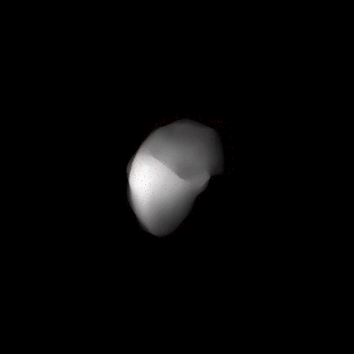
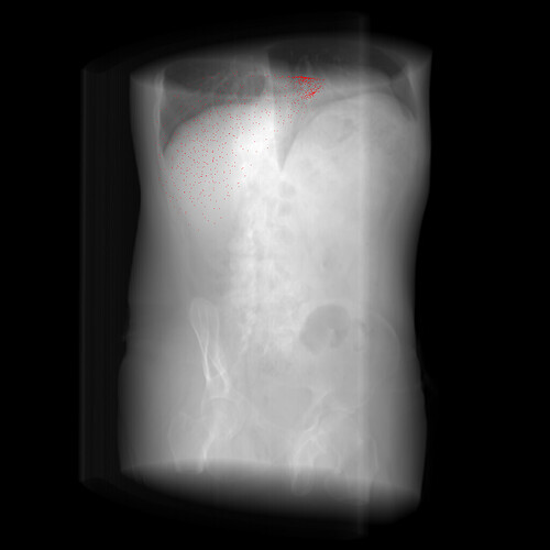
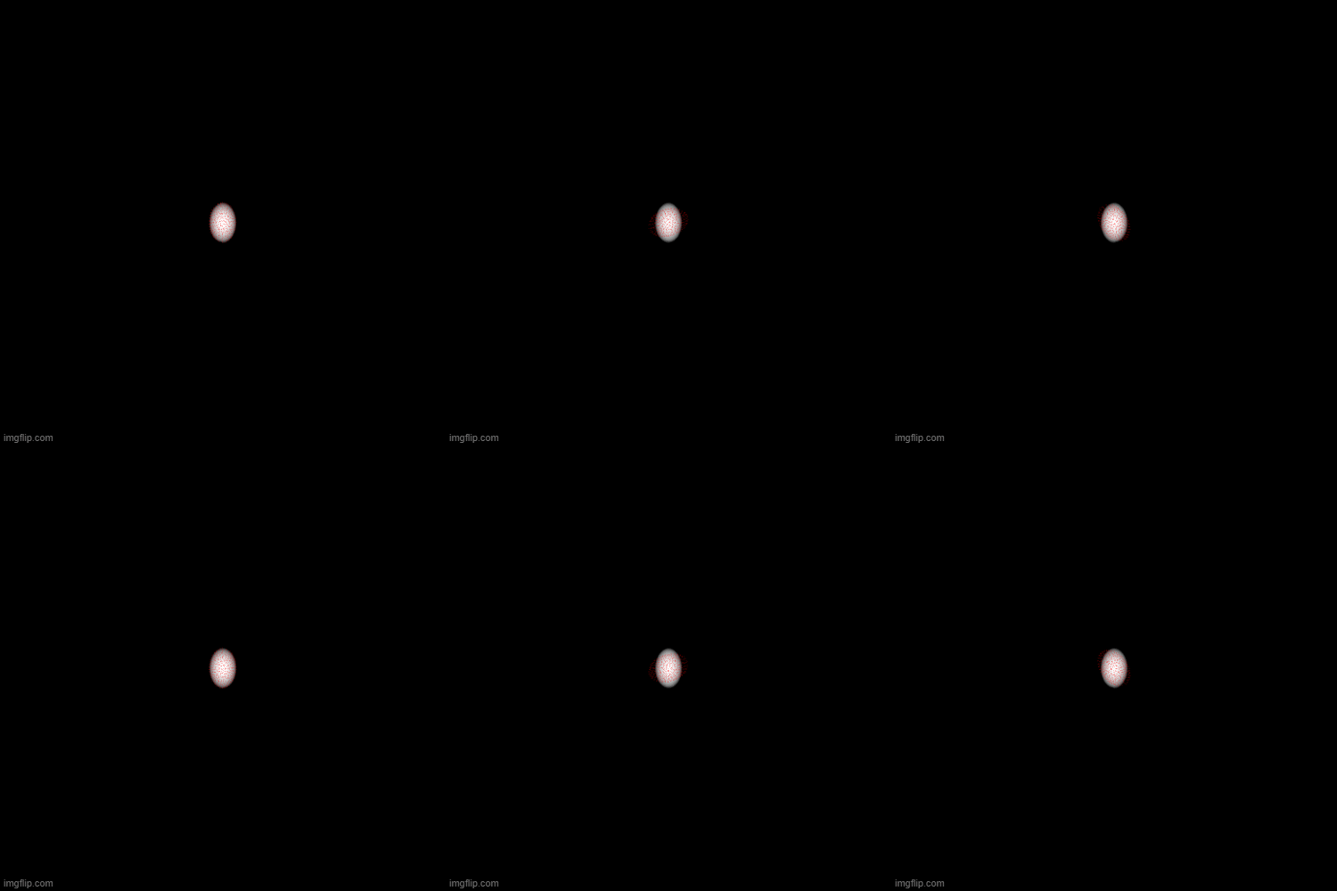
As you can see in the attached gif animation, the point cloud (see red dots) is rotate around wrong direction compared to the DRR images. How can I fix it ?
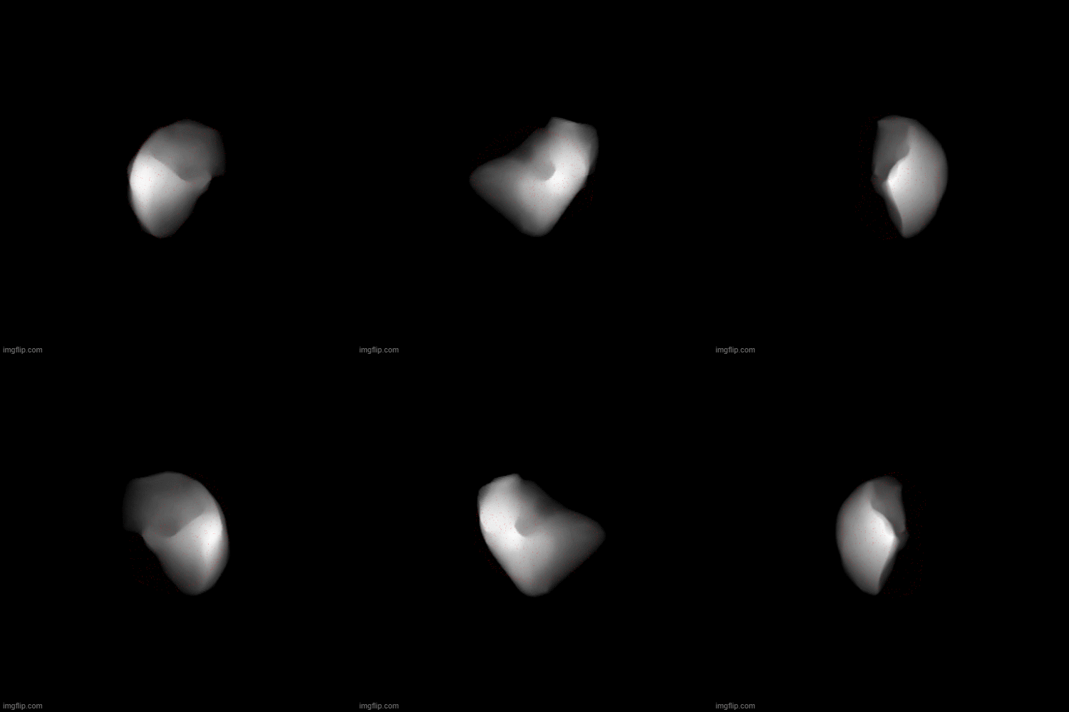
Another example with a volumetric ellipsoid.
def getDRRProjectionCoords(self, points=None, m_ProjectionAngle=0., m_FocalPointToIsocenterDistance=1000., m_Threshold=0.,
                               source_to_detector_distance=1536., im_sx=1., im_sy=1., dx=1024, dy=1024):

        # Use the image center as the central axis position.
        # refer https://github.com/InsightSoftwareConsortium/ITKTwoProjectionRegistration/blob/master/test/GetDRRSiddonJacobsRayTracing.cxx#L506-L510
        o2Dx = (dx - 1.) / 2.
        o2Dy = (dy - 1.) / 2.
        # constant for converting degrees into radians
        dtr = (math.atan(1.0) * 4.0) / 180.0
        Dimension = 3

        PointType = itk.Point[itk.D, Dimension]
        VectorType = itk.Vector[itk.D, Dimension]
        MatrixType = itk.Matrix[itk.D, Dimension, Dimension]
        TransformType = itk.Euler3DTransform[itk.D]

        # Compute the origin (in mm) of the 2D Image
        m_Origin = PointType()
        m_Origin[0] = -im_sx * o2Dx
        m_Origin[1] = -im_sy * o2Dy
        m_Origin[2] = m_FocalPointToIsocenterDistance - source_to_detector_distance

        m_Spacing = VectorType()
        m_Spacing[0] = im_sx  # pixel spacing along X of the 2D DRR image [mm]
        m_Spacing[1] = im_sy  # pixel spacing along Y of the 2D DRR image [mm]
        m_Spacing[2] = 1.0 # slice thickness of the 2D DRR image [mm]

        # inverse trasnform to rotate the vertex into DRR detector coordinate system
        # user can set an arbitrary transform for the volume. If not explicitly set, it should be identity.
        # Here I'm not setting the isocenter location and assume it is in (0, 0, 0) by default,
        # but in the DRR algorithm that we used to generate DRR images, Set the center of the 3D image volume (CT) as the isocenter
        # refer https://github.com/InsightSoftwareConsortium/ITKTwoProjectionRegistration/blob/master/test/GetDRRSiddonJacobsRayTracing.cxx#L452-L454
        m_Transform = TransformType.New()
        m_Transform.SetComputeZYX(True)
        m_Transform.SetIdentity()

        m_InverseTransform = TransformType.New()
        m_InverseTransform.SetComputeZYX(True)

        m_ComposedTransform = TransformType.New()
        m_ComposedTransform.SetComputeZYX(True)

        m_GantryRotTransform = TransformType.New()
        m_GantryRotTransform.SetComputeZYX(True)
        m_GantryRotTransform.SetIdentity()

        m_CamShiftTransform = TransformType.New()
        m_CamShiftTransform.SetComputeZYX(True)
        m_CamShiftTransform.SetIdentity()

        m_CamRotTransform = TransformType.New()
        m_CamRotTransform.SetComputeZYX(True)
        m_CamRotTransform.SetIdentity()
        m_CamRotTransform.SetRotation(dtr * (-90.0), 0.0, 0.0)

        m_ComposedTransform.SetIdentity()
        m_ComposedTransform.Compose(m_Transform, False)

        # isocenter set to (0, 0, 0)
        # but in the DRR algorithm that we used to generate DRR images, Set the center of the 3D image volume (CT) as the isocenter
        isocenter = m_Transform.GetCenter()

        # An Euler 3D transform is used to rotate the volume to simulate the roation of the linac gantry.
        # The rotation is about z-axis. After the transform, a AP projection geometry (projecting
        # towards positive y direction) is established.
        m_GantryRotTransform.SetRotation(0.0, 0.0, dtr * (-m_ProjectionAngle))
        m_GantryRotTransform.SetCenter(isocenter)
        m_ComposedTransform.Compose(m_GantryRotTransform, False)

        # An Euler 3D transfrom is used to shift the camera to the detection plane
        camtranslation = VectorType()
        camtranslation[0] = -isocenter[0]
        camtranslation[1] = -isocenter[1]
        camtranslation[2] = source_to_detector_distance - m_FocalPointToIsocenterDistance - isocenter[2]
        #print(camtranslation)
        m_CamShiftTransform.SetTranslation(camtranslation)
        m_ComposedTransform.Compose(m_CamShiftTransform, False)

        # An Euler 3D transform is used to establish the standard negative z-axis projection geometry. (By
        # default, the camera is situated at the origin, points down the negative z-axis, and has an up-
        # vector of (0, 1, 0).)
        m_ComposedTransform.Compose(m_CamRotTransform, False)

        # The overall inverse transform is computed. The inverse transform will be used by the interpolation
        # procedure.
        m_ComposedTransform.GetInverse(m_InverseTransform)

        MatrixType = itk.Matrix[itk.D, Dimension, Dimension]

        m_Direction = MatrixType()
        m_Direction.SetIdentity()

        m_IndexToPhysicalPoint = MatrixType()
        m_IndexToPhysicalPoint.SetIdentity()

        m_PhysicalPointToIndex = MatrixType()
        m_PhysicalPointToIndex.SetIdentity()

        scale = MatrixType()

        # Compute helper matrices used to transform Index coordinates to
        # PhysicalPoint coordinates and back. This method is virtual and will be
        # overloaded in derived classes in order to provide backward compatibility
        # behaviour in classes that did not used to take image orientation into
        # account.
        scale = itk.GetMatrixFromArray(np.diag(m_Spacing))
        m_IndexToPhysicalPoint = m_Direction * scale
        m_PhysicalPointToIndex = m_IndexToPhysicalPoint.GetInverse()

        # this entire bottom part should be iterated over all the points
        tesnor_to_numpy_ = points.cpu().detach().numpy()
        point_list = tesnor_to_numpy_.tolist()

        # hold the pixel cooridnates as separate numpy arrays for x and y coordinates
        u = np.array([])
        v = np.array([])

        for point in point_list:
            # coordinate to the coordinate system defined by the detector coordinate system
            drrPixelWorld = m_InverseTransform.TransformPoint(point)
            #print(drrPixelWorld)
            # 2D coordinates on the detector plane (in physical units, not in pixels)
            # calculate the physical cooridante in DRR image plane
            # i.e. multiply the x and y coordinates by the ratio source-to-detector distance over z
            drrPixelWorld[0] = drrPixelWorld[0] * (source_to_detector_distance/(source_to_detector_distance+drrPixelWorld[2]))
            drrPixelWorld[1] = drrPixelWorld[1] * (source_to_detector_distance/(source_to_detector_distance+drrPixelWorld[2]))
            drrPixelWorld[2] = -536
            #print(drrPixelWorld)

            index = VectorType()
            for i in range(Dimension):
                sum = itk.NumericTraits[itk.D].ZeroValue()
                for j in range(Dimension):
                    sum += m_PhysicalPointToIndex(i, j) * (drrPixelWorld[j] - m_Origin[j])
                index[i] = sum

            u = np.append(u, index[0])
            v = np.append(v, index[1])


return u, vI don’t think the problem is with m_Direction. Your ellipsoid example clearly indicates that you’re not rotating correctly. Have you tried, e.g., adjusting m_GantryRotTransform to rotate around another axis?
I have rotated around other two axises as well. But it does not work well.
I’m not sure why the rotation around z-axis is not working since I have implemented this very similar to the Siddon-Jacob ray-tracing algorithm and this works perfectly well for gantry angle zero.
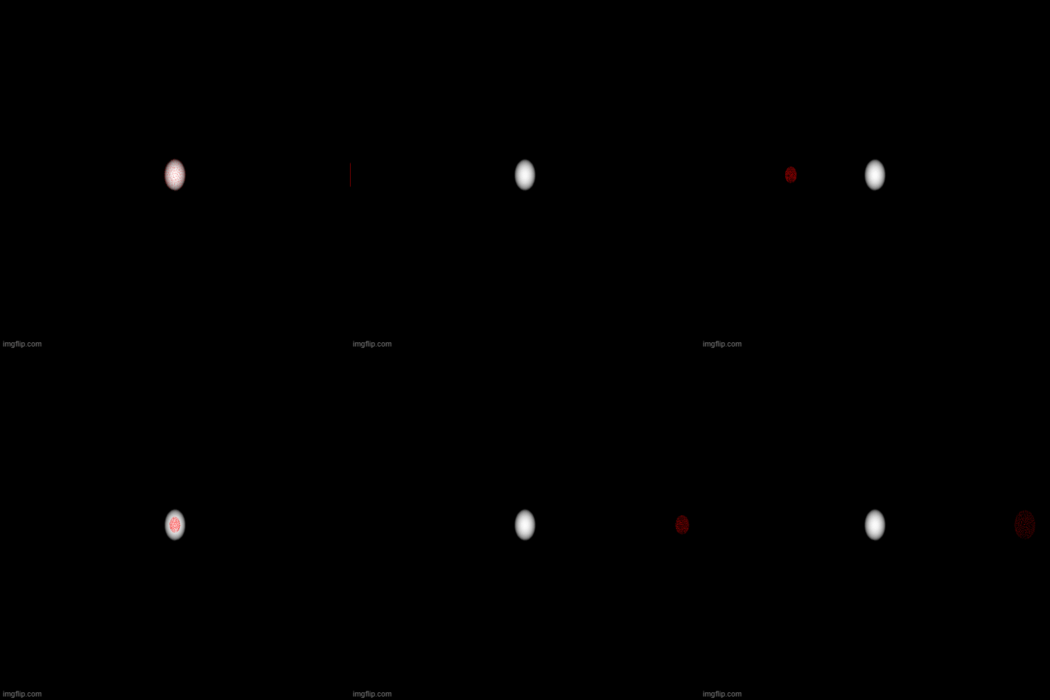
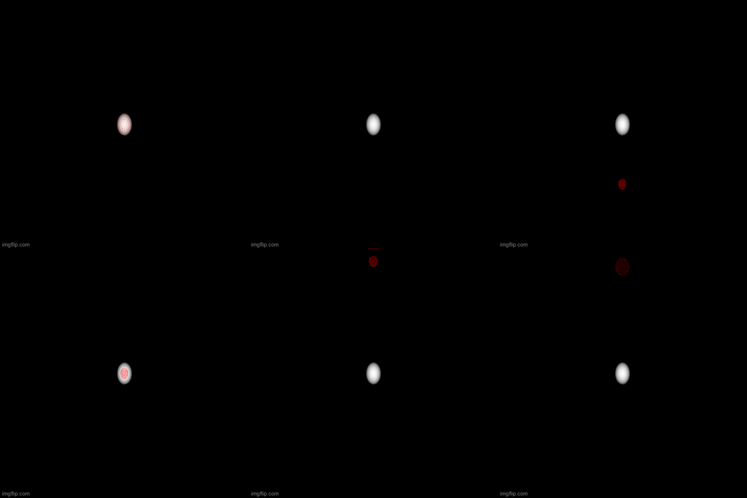
Please see the results for rotating around around y and x-axises.
m_GantryRotTransform.SetRotation(0.0, dtr * (-m_ProjectionAngle), 0.0)
m_GantryRotTransform.SetRotation(dtr * (-m_ProjectionAngle), 0.0, 0.0)
Hi Simon,
I guess I should first rotate 90◦ around the x-axis followed by gantry rotation (i.e. dtr * m_ProjectionAngle) around the z-axis according to the order given in the attached image.
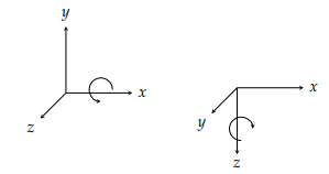
I have added one single line of code as below to the existing code before rotating with the gantry angle (i.e. rotate dtr * (-m_ProjectionAngle) around z-axis).
# rotate 90◦ around the x-axis
m_GantryRotTransform.SetRotation(dtr * (-90.0), 0.0, 0.0)
But nothing changed as expected and the result is like in the earlier case. How can I do that kind of rotation ? Please let me know if I’m wrong. I need your help to fix this issue.
I admit I don’t know. I guess the center of rotation is around (0,0,0) mm so I would make sure that the ellipsoid is centered around this point. Other than that, I have no suggestion, I would need a complete minimal example to help you solve your geometric issue.
(post deleted by author)
Hi Simon,
I feel sorry for bothering you again. I have attached above a minimal complete reproducible example code with the data as you requested last week.
Can I ask any possible solution to my issue please ? Thanks in advance for your time and consideration.
I finally managed to look briefly at it. It’s not obvious what you’re doing but here is a patch which seems to help: minimal_working_code.py. I kept the transforms in a natural order to me: gantry rotation then camera translation then camera rotation. I also changed the camera rotation, having a rotation around x is really not natural. I believe this explained the weird effects you had when changing the axis around which you were rotating. I instead combined two rotations of the gantry. I do not fully remember how you compute those DRRs but eventually you should be able to understand the two geometries. I will not have more time to dedicate to this but I hope my attempt will help you… Good luck!
Hi Simon,
Thank you very much for your support on this matter, I really appreciate it. Actually atleast this is now perfectly align for symmetric objects like ellipsoid, cube, etc.
This code will be used to project the predicted liver mesh geometry on to the corresponding DRR image to check their alignments. Before doing that I need to test this with the actual data. That is what I’m currently attempting to address with this implementation.
I have one last question. When I project the point cloud of my dummy liver case and the real case scenario (which consist of assymetric geometry), they are not aligned with the correposnding DRR image.
I have attached few images of the point clouds projected on the corresponding DRR images and the Syddon-Jacob DRR code to generate DRR images for your further reference. Could you please help me on this matter as well.
siddon_jacob_raytracing.py (5.8 KB)
I was not clear, sorry, I meant in the code. I think you should use the composed transform and not the inverse. In the C++ code you mimicked in Python, they have a transform to go from DRR coordinates to world. You want to do the opposite, go from work to DRR coordinates.
Thanks for providing the code for generating the DRRs. Here is a new version of your minimal example where I try to do exactly the same thing (including the flip), minimal_working_code.py (9.6 KB), does it work better for you?
Many thanks, now there is a small misalignment issue with the projected points and the corresponding DRR image.
I think it is due to the image origin issue, but not sure. The reason because in the Siddon-Jacob’s fast ray-tracing algorithm, it forces the origin of the CT image to be (0,0,0). You can see it in the DRR image generation code.
Therefore, I have changed the imOrigin in the updated projection code that you have been recently attached, but it is not working perfectly well.
I here attached the point clouds projected on the corresponding DRR images for your further reference.
I noticed the offset too. Can you indicate where in the code they reset the origin to 0 please?
Here it is in C++ version.
I guess it is a flipping issue. isn’t it ? When I compared volumetric_liver_0_aligned.png and volumetric_liver_180_aligned.png images with the projected points (see in the attached zip file above), the mesh points projected on the 180 degree gantry angle may be flipped on the x direction to align with the DRR image with 0th degree gantry angle. Please correct me if I’m wrong.
No I don’t think it’s the problem. In this new version, I do it more closely to the code, I do the equivalent of setting the origin at 0 with a translation of -origin, but then the isocenter is modified accordingly so it cancels out.
I don’t think so. Actually, I checked again and the projection never occurs in the code I had sent. I think the correct way of doing the projection is in this version minimal_working_code.py (9.6 KB). This is based on the observation that in the detector coordinate system, the source is at (0,0,0):
Maybe the final solution?
Yes, it is the final solution. Thank you very much for the help you gave me for this issue. I greatly appreciate the assistance you have provided me. Thanks again.
