Resample to same Spacing and Size and Align to same Origin

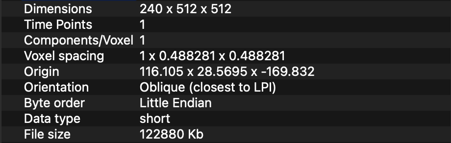
I have a set of 4 DICOM CT Volumes which I am reading with SimpleITK ImageSeriesReader. Two of the images represent the CT of patient before and after the surgery. The other two images are binary segmentation masks segmented on the former 2 CT images. The segmentations are a ROI of their source CT.

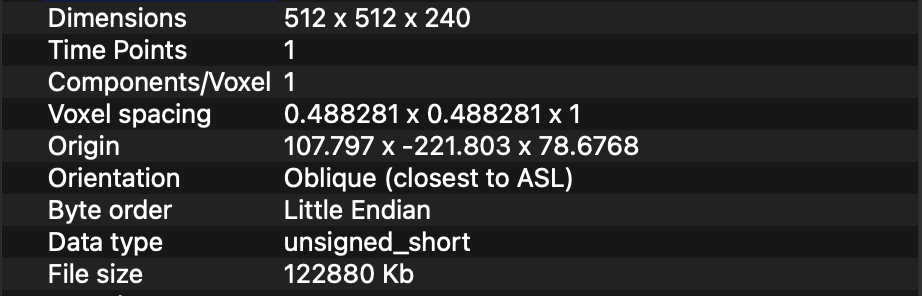
All the 4 CT images, have different Size, Spacing, Origin and Direction. I have tried applying this GitHub gist https://gist.github.com/zivy/79d7ee0490faee1156c1277a78e4a4c4 to resize my images to 512x512x512 and Spacing 1x1x1. However, it seems to only work for the source CT images. It doesn’t work on the segmentation images. The segmented structure is always placed in the center of the CT image, instead of the correct location.

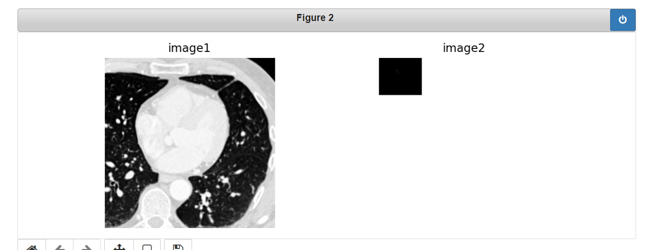
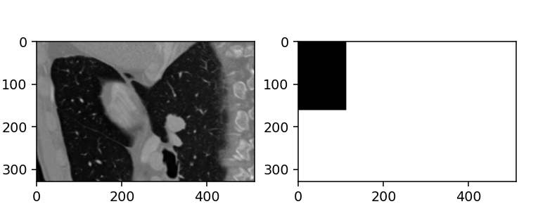
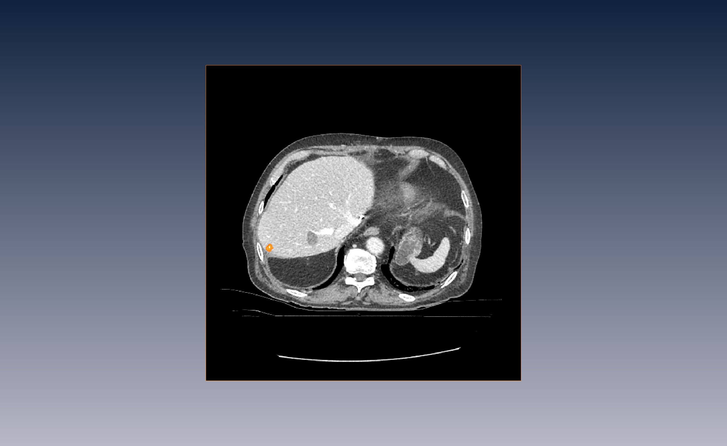
This are my “raw” image with its corresponding segmentation.

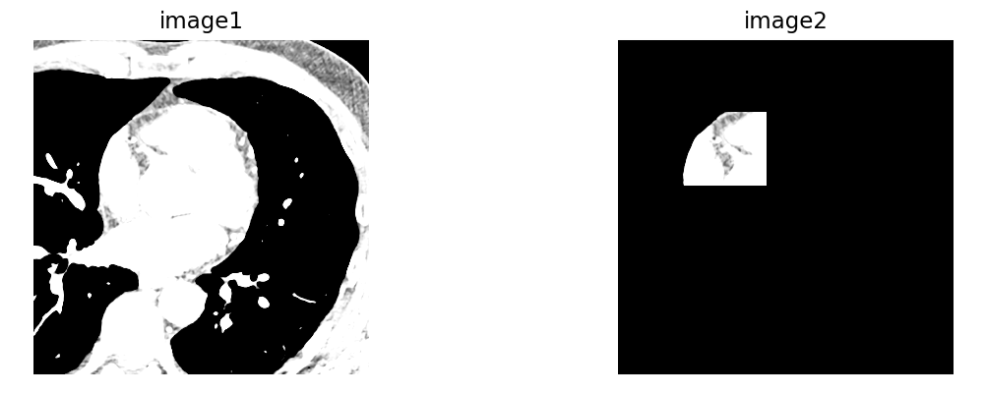
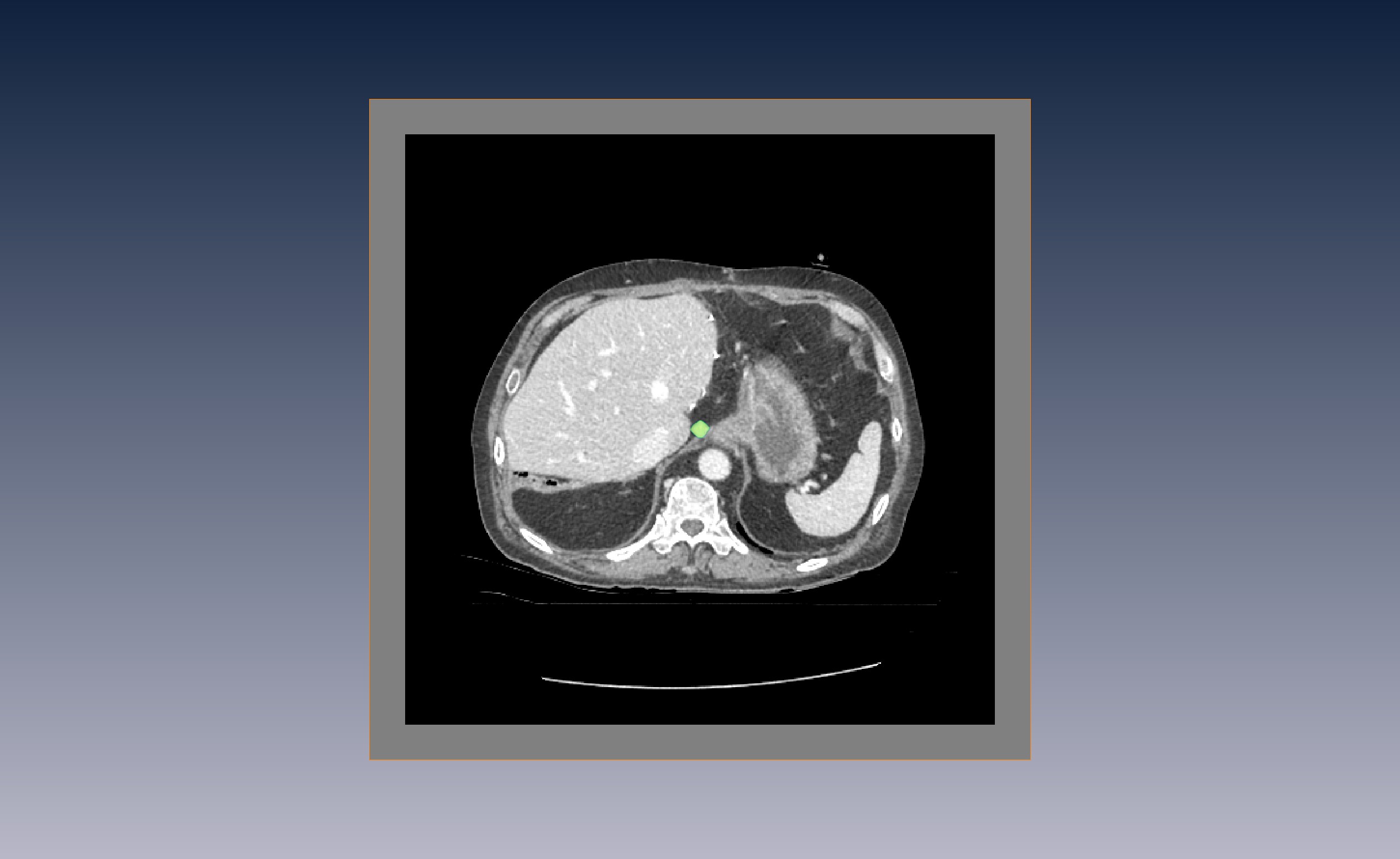
And this is the result which is obviously incorrect.

This is my code:
def resize_resample_images(images):
#Define tuple to store the images
tuple_resized_imgs = collections.namedtuple('tuple_resized_imgs', ['img_plan', 'img_validation', 'ablation_mask', 'tumor_mask'])
# %% Create Reference image with zero origin, identity direction cosine matrix and isotropic dimension
dimension = images.img_plan.GetDimension()
reference_direction = np.identity(dimension).flatten()
reference_size_x = 512
reference_origin = np.zeros(dimension)
data = [images.img_plan, images.img_validation, images.ablation_mask, images.tumor_mask]

reference_physical_size = np.zeros(dimension)
for img in data:
    reference_physical_size[:] = [(sz - 1) * spc if sz * spc > mx else mx for sz, spc, mx in
                                  zip(img.GetSize(), img.GetSpacing(), reference_physical_size)]
reference_spacing = [reference_physical_size[0] / (reference_size_x - 1)] * dimension
reference_size = [int(phys_sz/(spc) + 1) for phys_sz,spc in zip(reference_physical_size, reference_spacing)]

reference_image = sitk.Image(reference_size, images.img_plan.GetPixelIDValue())
reference_image.SetOrigin(reference_origin)
reference_image.SetSpacing(reference_spacing)
reference_image.SetDirection(reference_direction)
reference_center = np.array(
    reference_image.TransformContinuousIndexToPhysicalPoint(np.array(reference_image.GetSize()) / 2.0))
data_resized = []
for idx,img in enumerate(data):
    #%% Set Transformation
    transform = sitk.AffineTransform(dimension) # use affine transform with 3 dimensions
    transform.SetMatrix(img.GetDirection()) # set the cosine direction matrix
    # TODO; set the center correctly
    # transform.SetCenter(reference_center)
    transform.SetTranslation(np.array(img.GetOrigin()) - reference_origin) # set the translation.
    # Modify the transformation to align the centers of the original and reference image instead of their origins.
    centering_transform = sitk.TranslationTransform(dimension)
    img_center = np.array(img.TransformContinuousIndexToPhysicalPoint(np.array(img.GetSize()) / 2.0))
    centering_transform.SetOffset(np.array(transform.GetInverse().TransformPoint(img_center) - reference_center))
    centered_transform = sitk.Transform(transform)
    centered_transform.AddTransform(centering_transform)

    #%% set all  output image parameters: origin, spacing, direction, starting index, and size.
    resampler = sitk.ResampleImageFilter()
    resampler.SetReferenceImage(reference_image)
    resampler.SetDefaultPixelValue(img.GetPixelIDValue())
    resampler.SetTransform(centered_transform)
    resampler.SetSize(reference_image.GetSize())
    resampler.SetOutputSpacing(reference_image.GetSpacing())
    resampler.SetOutputOrigin(reference_image.GetOrigin())
    resampler.SetOutputDirection(reference_image.GetDirection())
    if idx==0 or idx==1:
        resampler.SetInterpolator(sitk.sitkLinear)
    elif idx==2 or idx==3:
        resampler.SetInterpolator(sitk.sitkNearestNeighbor)
    resampled_img = resampler.Execute(img)
    data_resized.append(resampled_img)
resized_imgs = tuple_resized_imgs(img_plan=data_resized[0],
                                  img_validation=data_resized[1],
                                  ablation_mask=data_resized[2],
                                  tumor_mask=data_resized[3])
return resized_imgs

I believe this Jupyter notebook does what you are looking for (sample multiple intensity images of various sizes onto the same sized image and do the same with segmentations).

Let me know if this doesn’t address your needs and I’ll take a closer look at your code.

Hi , thank for your reply. I did follow that notebook. I assume the “Create reference domain” is the part that interests me.

I assume something is incorrect with my transformation, because the segmentation mask is always place in the center. Possibly with my centering transform, but I can’t tell exactly what.

So I still get the inccorect placement of the segmentation.
I am providing the dimensions of the 2 images displayed in the pictures if it helps.
SEGMENTATION :
image mask direction (1.0, 0.0, 0.0, 0.0, 1.0, 0.0, 0.0, 0.0, 1.0)
image mask origin (-119.89099884033203, 29.718700408935547, -1002.7899780273438)
mask spacing (0.892, 0.892, 0.79998779296875)
segmentation size (17, 16, 16)
IMAGE SOURCE:
image direction (1.0, 0.0, 0.0, 0.0, 1.0, 0.0, 0.0, 0.0, 1.0)
image origin (-204.63099670410156, -228.06930541992188, -1170.0)
image spacing (0.892, 0.892, 0.800048828125)
image size (512, 512, 381)

I expected the size of the segmentation mask to be the same as the image. That is what the original code in the notebook assumed. Does the original segmentation have a different size/origin than the image? If yes, then the centering of the volumes is probably the culprit (try removing that).

Also, the condition for selecting interpolator is strange, when idx==1 it will always be nearest neighbor so not sure why it also appears in the ‘if’ statement:

    if idx==0 or idx==1:
        resampler.SetInterpolator(sitk.sitkLinear)
    elif idx==1 or idx==3:
        resampler.SetInterpolator(sitk.sitkNearestNeighbor)

Yes, the segmetation mask has a different size, origin and spacing.
I also assumed that the centering of the volumes is the culprit so I removed it. However I obtained only grey images after removing the centering. Maybe I am outside the physical space of the reference image.

As a solution to the different size, I was thinking to use SimpleITK.Paste(*args), to paste the mask in the same size as its source. But I didn’t find whether it preserves the spacing and the other parameters.

Also, thank you, you pointed out correctly that the condition is wrong.
I am storing the images and their segmentation mask in a tuple. So at index=0 and index=1 will be the original CT images so I want to apply Linear Interpolation. for the binary segmentation masks stored at index 2 and 3 in the tuple I want to use NearestNeighbor Interpolator.

Use Paste if the original image and segmentation have the same spacing (I assume the segmentation was obtained on the original image so this is likely).

If this isn’t the case then use resample with identity transformation, zero as the default pixel value, and nearest neighbor interpolation (assuming here that the origin of the original segmentation places it in the correct location with respect to the original image):

new_segmentation = sitk.Resample(original_segmentation, original_image.GetSize(),
                                 sitk.Transform(), 
                                 sitk.sitkNearestNeighbor,
                                 original_image.GetOrigin(),
                                 original_image.GetSpacing(),
                                 original_image.GetDirection(),
                                 0,
                                 original_segmentation.GetPixelID())
1 Like

Thank you.
Some of the segmentation files have the same spacing as their original image, some do not. So I used PASTE if the spacing was similar and RESAMPLE if the spacing differed. Then I applied the Transformations and Resampled again to move them in the same space and have similar spacing for all the images.

It seems everything is working (by visually assessing it), however I get some grey slices towards the end of the CT stack (assuming counting in z-direction starting index 0). Is that correct? I assume it’s because a number of CT have less slices than the Reference size they were resampled on. I am sorry if this something obvious, I am just starting with medical images processing.

This approach sounds reasonable to me (I may be biased as I pointed you in this direction).

You are doing well for someone who has just started with medical imaging, hopefully the following will move you further along:

The main difference between medical images and other types of images is that they are
spatial objects. That is, the CT image occupies a specific region in space with a
known size (think of it as a box in 3D space).

This brings us to your question with respect to grey slices. The reference_image represents
a box of certain dimensions (sizes*spacings), the largest size of expected patients, so that everyone will
fit into this box without distorting their physical size. When you have a smaller patient they fit in the box with space to spare (grey slices). As a sanity check you can measure structures in the original CT and in your resampled CT and see that their size remained the same (fewer/more pixels but larger/smaller spacing between them).

As you are working with CT: during the initial code development it is good that you get these
grey slices, showing you where the original data existed and where you were looking outside
of the original (grey). When you are happy with the code you should switch to a more appropriate
value, in the case of CT, a value of -1000 (Hounsfield value for air).

Looking at the code, you have:

resampler.SetDefaultPixelValue(img.GetPixelIDValue())

This is incorrect usage of the SetDefaultPixelValue method. The GetPixelIDValue referes to the type of the
pixel which unfortunately is a number and thus accepted by the method without complaints. If you don’t set
it, the default is zero, any arbitrary value you use is fine (including whatever GetPixelIDValue returned).

2 Likes

Hello,
I have the similar issue with some CT(.dcm) files and the segmentation files(.nrrd) being in different properties.
For CT images:
Origin: ( -197.62109375, -340.62109375, -506.0),
Spacing: (0.7578125, 0.7578125, 3.0),
Size: (512, 512, 160),
Direction:
(1.0, 0.0, 0.0
0.0, 1.0, 0.0,
0.0, 0.0, 1.0),
DataType: ‘16-bit signed integer’

For segmentation masks:
Origin: (-29.18254994612613, -213.1412436358888, -297.9970796235392, 0.0)
Spacing: (0.699981689453125, 0.699981689453125, 0.699981689453125, 1.0)
Size: (102, 149, 359, 3)
Direction:
(1.0, 0.0, 0.0, 0.0,
0.0, 1.0, 0.0, 0.0,
0.0, 0.0, 1.0, 0.0,
0.0, 0.0, 0.0, 1.0)
DataType: ‘32-bit float’

I am new to using both .dcm and .nrrd file types so not sure why the segmentation mask has 4 dimensions.
I would like to have both image and segmentation masks in the same size, spacing, and paired to each other. So that I can visualize or process image/mask.

Hello @banikr,

The segmentation masks are not as expected. For some reason the pixel type is floating point which isn’t natural for segmentation masks which are integer by nature.

I suspect that the 4D segmentation image includes three masks (last three channels) that represent three or more likely overlapping labels. This is just a guess as you haven’t provided enough details with respect to the segmentation mask. The most common situation is when the masks/labels are not overlapping and you only need a single volume to represent the segmentation.

Also, the segmentation spacing and size do not match that of your CT, so you will need to resample the segmentation onto the CT grid in order to visualize it yourself. If you load both into 3D Slicer and they overlap, you will see it (Slicer does the resampling under the hood before display). For more details on combining images and segmentations for visualization in SimpleITK see this notebook.

1 Like

If your mask image has float pixels, it is most likely a fractional label map. And probably represents 3 objects, based on size.

1 Like

composition.multi.nrrd (3, 210, 113, 129)
lumenPartition.multi.nrrd (1, 210, 113, 129)
lumenSegmentation.nrrd (210, 113, 129)
wallPartition.multi.nrrd (1, 210, 113, 129)
wallSegmentation.nrrd (210, 113, 129)
wallThickness.nrrd (210, 113, 129)
composition.multi.nrrd (3, 210, 113, 129)
deblurredImage.nrrd (210, 113, 129)
deblurredImage.stage1.nrrd (210, 113, 129)
lumenPartition.multi.nrrd (1, 210, 113, 129)
lumenSegmentation.nrrd (210, 113, 129)
capThickness.nrrd (210, 113, 129)
composition.multi.nrrd (5, 210, 113, 129)
lumenPartition.multi.nrrd (1, 210, 113, 129)
lumenSegmentation.nrrd (210, 113, 129)
periRegPartition.multi.nrrd (1, 210, 113, 129)
perivascularRegion.nrrd (210, 113, 129)
wallPartition.multi.nrrd (1, 210, 113, 129)
wallSegmentation.nrrd (210, 113, 129)
wallThickness.nrrd (210, 113, 129)
subvol.nrrd (210, 113, 129)
wallPartition.multi.nrrd (1, 210, 113, 129)
wallSegmentation.nrrd (210, 113, 129)
wallThickness.nrrd (210, 113, 129)

These are the .nrrd files I have against one set of Dicom files. Yeah, you are right that these are not actually segmentation masks. These are level set distance maps.
I am not familiar with these types of files against anatomical images(CT) or how to interpret them and get the spatial info. All I see are blurred images in ITK or other image visualization software. Some of them have 4 dimensions but this dimension(210, 113, 129) is same in all images.
Let me know what other details would help to understand the files.

I don’t know a tool which keeps segmentations as distance maps. But you can go to binary segmentations by thresholding the distance maps at value 0.0. I don’t know about 4D ones - try looking at them using the sequences extension.

1 Like

Hello,
with the image and segmentation as below:
CTsize → (512, 512, 427)
Origin : (-64.3056640625, -296.3056640625, -256.5)
Spacing : (0.388671875, 0.388671875, 0.30000000000000004)
Direction : (1.0, 0.0, 0.0, 0.0, 1.0, 0.0, 0.0, 0.0, 1.0)

Lusize → (129, 113, 210)
Origin : (-26.2158203125, -253.1630859375, -227.1011962890625)
Spacing : (0.388671875, 0.388671875, 0.29998779296875)
Direction : (1.0, 0.0, 0.0, 0.0, 1.0, 0.0, 0.0, 0.0, 1.0)

I ran the following code to align both images in the same size, space, origin and superimposed on each other to create paired (image-segmentation) data.

  def resize_resample_images(data): #, cen_trans=None):
    #Define tuple to store the images
    #tuple_resized_imgs = collections.namedtuple('tuple_resized_imgs', ['img_plan', 'img_validation', 'ablation_mask', 'tumor_mask'])
    # %% Create Reference image with zero origin, identity direction cosine matrix and isotropic dimension
#     data = [image1, image2]
    dimension = data[0].GetDimension()
    reference_direction = np.identity(dimension).flatten()
    reference_size_x = 512 # why? 
    reference_origin = np.zeros(dimension)
    #data = [images.img_plan, images.img_validation, images.ablation_mask, images.tumor_mask]
    reference_physical_size = np.zeros(dimension)
    for img in data:
        reference_physical_size[:] = [(sz - 1)*spc if sz*spc > mx else mx for sz,spc,mx in zip(img.GetSize(), img.GetSpacing(), reference_physical_size)]
    print(reference_physical_size) #  [198.61132812 198.61132812 127.8       ]
    reference_spacing = [reference_physical_size[0] / (reference_size_x - 1)] * dimension
    print("reference spacing: ", reference_spacing)
    reference_size = [int(phys_sz/(spc) + 1) for phys_sz,spc in zip(reference_physical_size, reference_spacing)]
    reference_image = sitk.Image(reference_size, data[0].GetPixelIDValue()) # why?
    reference_image.SetOrigin(reference_origin)
    reference_image.SetSpacing(reference_spacing)
    reference_image.SetDirection(reference_direction)
    reference_center = np.array(reference_image.TransformContinuousIndexToPhysicalPoint(np.array(reference_image.GetSize()) / 2.0))
    print("rc:", reference_center)
    data_resampled = []
    for idx,img in enumerate(data):
        #%% Set Transformation
        transform = sitk.AffineTransform(dimension) # use affine transform with 3 dimensions
        transform.SetMatrix(img.GetDirection()) # set the cosine direction matrix
        # TODO; set the center correctly
        transform.SetCenter(reference_center)
        transform.SetTranslation(np.array(img.GetOrigin()) - reference_origin) # set the translation.
        # Modify the transformation to align the centers of the original and reference image instead of their origins.
#         if cen_trans: # is not None: 
        centering_transform = sitk.TranslationTransform(dimension)
#         print(centered_transform)
        img_center = np.array(img.TransformContinuousIndexToPhysicalPoint(np.array(img.GetSize()) / 2.0))
        centering_transform.SetOffset(np.array(transform.GetInverse().TransformPoint(img_center) - reference_center))
        centered_transform = sitk.Transform(transform)
#         centered_transform.AddTransform(centering_transform)

        #%% set all  output image parameters: origin, spacing, direction, starting index, and size.
#     centered_transform = sitk.Transform(transform)
#     for idx,img in enumerate(data):
        resampler = sitk.ResampleImageFilter()
        resampler.SetReferenceImage(reference_image)
        resampler.SetDefaultPixelValue(img.GetPixelIDValue())
        resampler.SetTransform(centered_transform)
        resampler.SetSize(reference_image.GetSize())
        resampler.SetOutputSpacing(reference_image.GetSpacing())
        resampler.SetOutputOrigin(reference_image.GetOrigin())
        resampler.SetOutputDirection(reference_image.GetDirection())
        if idx==0: # or idx==1:
#             print("Here1")
            resampler.SetInterpolator(sitk.sitkLinear)
        elif idx==1: # or idx==3:
#             print("Here")
            resampler.SetInterpolator(sitk.sitkNearestNeighbor)
        resampled_img = resampler.Execute(img)
        data_resampled.append(resampled_img)
    resampled_imgs = [data_resampled[0], data_resampled[1]] 
    return resampled_imgs 

The result has same origin and size but the results do no overlap properly.


Taking other slice:

How do I orient both larger image and smaller segmentation files on top of each other so that segmentation labels match with corresponding image voxels.

Also

    reference_image = sitk.Image(reference_size, data[0].GetPixelIDValue()) # why?

Why GetPixelIDValue() is taken while creating reference_image? which gives 2 for image and 8 for segmentation.

Hello @banikr,

Not sure what you are trying here. Are the centers of the image and segmentation volume supposed to be aligned? Generally speaking, there is no reason for it to be so. The common scenario is that the image and segmentation are in the same coordinate system (identity transformation) and for display purposes we resample the segmentation onto the image grid.

As a first step, load the image and segmentation in 3D slicer and see if they are aligned. If they are, then you only need to resample the segmentation onto the image grid. If they aren’t, you need to understand the input and use the appropriate, non-identity, transformation.

Yeah you are right.

aligned_lab = sitk.Resample(data[1], data[0], 
                            sitk.Transform(), 
                            sitk.sitkLinear, 
                            np.min(image).astype('double'), 
                            data[1].GetPixelID())

The code above did the job for me.

I wanted to know about data[1].GetPixedID() or data[1].GetPixelIDValue() what are these doing when I resample? I tried to find documentation but couldn’t get any.
For example, data[0].GetPixelIDValue() output is 2 and data[1].GetPixelIDValue() output is 8.
What do these mean and how do these impact resampling?
Thanks for replying.

Hello @banikr,

Please see the Doxygen based documentation.

The GetPixelID returns the constant enumerated type describing the pixel type (sitk.sitkUInt8, sitk.Float32 etc.). The GetPixelIDValue is just the integral value of that constant, rarely used.

Hello ITK Forum,

I am new to this forum - so my apologies for formatting errors, if any.

I had a problem similar to previous posters on this thread and wanted to ask for clarification. I am running a Computer Vision pipeline that requires Image/Mask data pair to be in the NIFTI format. I created image segmentation masks (two labels) for brain MRI data. The challenge is the masks were created using DICOM images. After converting images from DICOM to NIFTI using dcm2niix tool, the mask and image are not aligned.
I am attempting to align the mask to the images. Based on @zivy 's responses on multiple threads and utilizing the SimpleITK Jupyter Notebooks, I was able to write a code running affine/centered transforms, but unfortunately the resampled masks still remain misaligned, even though the image/mask parameters now match.
I utilized ITK for creating segmentations, and here is the image summary from ITK

  1. Segmentation Metadata

  2. NIFTI Metadata

Inspired by the original poster and @zivy , here is my code that I ran for obtaining what I thought were meaningful results (but it is not working)

print("Image Size Is : ",img.GetSize())
print("Image Origin Is : ",img.GetOrigin())
print("Image Spacing Is : ",img.GetSpacing())
print("Image Direction Is : ",img.GetDirection())

O/P : 
Image Size Is :  (240, 512, 512)
Image Origin Is :  (118.92853546142578, 107.12545776367188, -164.38722229003906)
Image Spacing Is :  (1.0, 0.48828125, 0.48828125)
Image Direction Is :  (-0.9942651651604811, 0.09239640166680871, -0.053848738074101433, -0.09226119079633939, -0.995722303134275, -0.004996775360453918, -0.05408007046262595, 2.917984276968692e-08, 0.9985366020551395)

#Print Size, Spacing, Origin and Direction of Segmentation

print("Seg Size Is : ",seg.GetSize())
print("Seg Origin Is : ",seg.GetOrigin())
print("Seg Spacing Is : ",seg.GetSpacing())
print("Seg Direction Is : ",seg.GetDirection())

O/P : 
Seg Size Is :  (512, 512, 240)
Seg Origin Is :  (128.5474090576172, -142.5655975341797, 84.75939178466797)
Seg Spacing Is :  (0.48828125, 0.48828125, 1.0)
Seg Direction Is :  (-0.09239640923107047, 0.053848738074101433, -0.9942651650166094, 0.9957223024323618, 0.004996775360453918, -0.09226119205650234, -2.927398818484832e-08, -0.9985366020551395, -0.05408007095786499)

#Code for Transform/Resampling : 
dimension = img.GetDimension()
reference_physical_size = np.zeros(dimension)

reference_physical_size[:] = [(sz)*spc if sz*spc>mx  else mx for sz,spc,mx in zip(img.GetSize(), img.GetSpacing(), reference_physical_size)]

# Create the reference image with a origin, direction and size same as the Image   
reference_origin = img.GetOrigin()
reference_direction = np.identity(dimension).flatten() #img.GetDirection()
reference_size = img.GetSize()
reference_spacing = [ phys_sz/(sz) for sz,phys_sz in zip(reference_size, reference_physical_size) ]

reference_image = sitk.Image(reference_size, img.GetPixelIDValue())
reference_image.SetOrigin(reference_origin)
reference_image.SetSpacing(reference_spacing)
reference_image.SetDirection(reference_direction)

reference_center = np.array(reference_image.TransformContinuousIndexToPhysicalPoint(np.array(reference_image.GetSize())/2.0))
# Transform which maps from the reference_image to the current img with the translation mapping the image
# origins to each other.
transform = sitk.AffineTransform(dimension)
transform.SetMatrix(seg.GetDirection())
transform.SetTranslation(np.array(seg.GetOrigin()) - reference_origin)
# Modify the transformation to align the centers of the original and reference image instead of their origins.
centering_transform = sitk.TranslationTransform(dimension)
seg_center = np.array(seg.TransformContinuousIndexToPhysicalPoint(np.array(seg.GetSize())/2.0))
centering_transform.SetOffset(np.array(transform.GetInverse().TransformPoint(seg_center) - reference_center))
#Composite Transform Method : https://simpleitk.readthedocs.io/en/master/migrationGuide2.0.html
centered_transform = sitk.CompositeTransform([transform,centering_transform])
# Using the linear interpolator as these are intensity images, if there is a need to resample a ground truth 
# segmentation then the segmentation image should be resampled using the NearestNeighbor interpolator so that 
# no new labels are introduced.
result = sitk.Resample(seg, reference_image, transform, sitk.sitkNearestNeighbor, 0.0)

I would sincerely appreciate any advice/help in this matter. Thank you for helping me learn!

Hello @Samarth,

These issues should not be addressed via resampling or applying a transformation. They are due to different axes conventions.

Based on the screen capture the segmentation dimensions are 512x512x240, but the image dimensions are 240x512x512, so axes don’t match. You can try the PermuteAxesImageFilter to change these so that they match (possibly sitk.PermuteAxes(seg,[2,1,0]).GetSize()).

2 Likes