I am segmenting an image, but when I apply a threshold filter there are some holes left in the surface that I need to fill. To fill in the holes I am using BinaryMorphologicalClosingImageFilter but it is very slow, even if I disable the SetSafeBorder (false) option it is still slow. Does Anyone know any other way to solve this problem faster?
Have you looked into the BinaryFillHoleImageFilter: https://itk.org/Doxygen/html/classitk_1_1BinaryFillholeImageFilter.html
This is an itk::LabelMap based filter.
I think that filter is for holes inside the image, I’m talking about holes on the surface, I need to close the edge of the image.
@ainor Maybe posting an image of the input data and your segmentation can help in understanding better what your problem is or what you consider to be a surface in the context of your problem. In fact, quoting the original post:
there are some holes left in the surface that I need to fill. To fill in the holes I am using BinaryMorphologicalClosingImageFilter but it is very slow,
@blowekamp 's suggestion is what you are looking for if you need to fill holes and are dealing with an image (be it 2D or 3D), as the mention to the itk::BinaryMorphologicalClosingImageFilter filter suggests. If by surface you mean boundary (or border), then itk::BinaryMorphologicalClosingImageFilter is still a valid option, as the hole filling will not do that job if I’m not mistaken (@blowekamp can correct me). Maybe sections 2.6.3 and 2.6.4 of the ITK SW Guide can be of help:
As for the speed issue, I do not think ITK offers other direct filters or faster means to achieve this.
1 Like
The grayscale morphology filter have faster implementation than the binary morphological filters in many cases. If you input image has just two value, then the binary and gray scale filters should be equivalent.
@richard.beare May be able to provide more details about this specific case.
2 Likes
There is an approximation of MorphologicalClosing, discussed here:
1 Like
Possibly use distance maps to approximate the closing operation (dilation followed by erosion)? This is pretty fast.
SimpleITK based code below:
distance_threshold = 1.0
sitk.SignedMaurerDistanceMap(sitk.SignedMaurerDistanceMap(binary_image, insideIsPositive=False, squaredDistance=False, useImageSpacing=True) < distance_threshold, insideIsPositive=False, squaredDistance=False, useImageSpacing=True)<-distance_threshold
5 Likes
We replaced all kernel-based morphological opening/closing (hole filling and removing of extrusions) and margin growing/shrinking operations with distance map based computations, because kernel-based implementations were several magnitudes slower when relatively large radius was used. For a kernel size of 21, kernel-based computation was at about 10-100x slower. Kernels would only have an advantage if you needed some custom shape (not sphere or ellipsoid), but such need has never been come up.
If it is important not to smooth surface features, just fill holes, then I would recommend to convert the labelmap to closed surface representation, perform shrink-wrapping, and convert back to labelmap. If you only want to fill holes at the surface (add a solid watertight shell) then you can create a shell from the solidified labelmap and merge that to the original labelmap (it will not fill internal holes then).
@ainor what is your end goal? 3D printing of bones? The SurfaceWrapSolidify extension in 3D Slicer was developed exactly for this task (it can even make bone printable in a way that fractures are preserved).
4 Likes
Hi All,
There are many things going on here that I’ll comment on as I’m still not entirely clear whether we’re talking about holes at the image boundary or a segmentation boundary. Also important is the size of the holes - hopefully the holes are “small” in some sense, otherwise anything we apply will mess up other parts of your segmentation
If the problem is about holes that cross the image boundary (i.e holes that are cropped by the field of view), then the simplest option is to probably to label the background and retain only small objects touching the boundary, then combine those with the original segmentation. The code is fiddly, but ought to be fast.
If the problem is holes in a segmentation that aren’t filled by the fill hole filter - I’d interpret these as errors in the segmentation then there are a couple of ideas you might look at. The comments so far have looked at various forms of filtering of the mask, and that is reasonable. If speed is the goal then consider the following - using grayscale morphology filters with the Box structuring element. These will be fast and independent of size of kernel. However the results may be too jagged for your application. There’s also a polygon structuring element that attempts to approximate disk/spherical structuring elements with lines. These aren’t great in 3D, but may help.
The parabolic morphology tools may also be worth a look. These do fast morphology with spherical structuring elements on binary or label images. Also fast distance transforms.
Both of these options will have runtime that is largely independent of kernel size.
Finally, perhaps filtering before segmentation will solve some of the problems. If the problem is caused by light or dark holes in grayscale, perhaps the grayscale hole filling will do the job. Let us know the segmentation procedure and perhaps we can advise on tweaks to that which will make the problem disappear.
2 Likes
Hi everyone: @jhlegarreta , @blowekamp , @dzenanz , @zivy , @lassoan , @richard.beare .
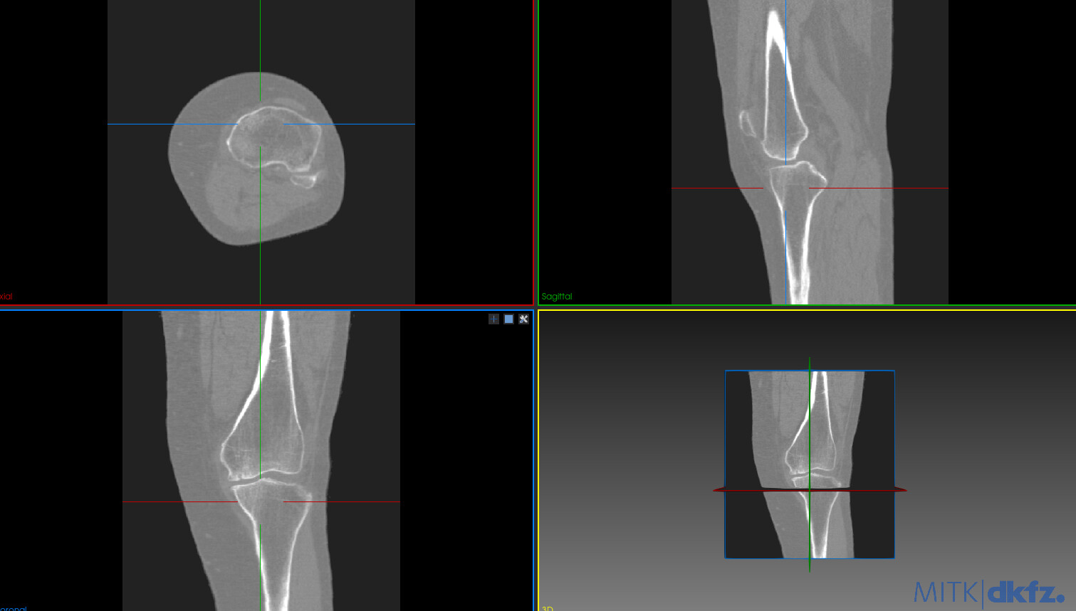
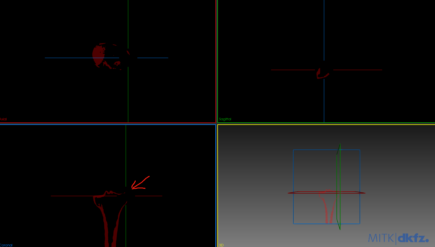
My goal is to separate the femur and tibia and get a good segmentation of both automatically with ITK. I have been able to do a first segmentation of both bones using OtsuMultipleThresholdsFilterType but the results have some holes on the surface, the biggest problem is the tibia.
Next I share a photo of the image that I want to segment and a photo of the segmented tibia.
I also share the nrrd files.
I am sorry by the questions but I am a little new in this.
Hi,
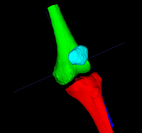
Segmentation of real structures is never easy. Here are some ideas that I usually explore first when basic thresholding doesn’t work. Usually I look at other approaches to the segmentation before thinking about fixing the segmentation. The best way to go depends on whether you want a solid object or a shell with the high density bone only (i.e. marrow not labelled). I’ve attached some examples of how to begin creating a solid structure, using filtering and my go-to tool for initial exploration - watershed transforms.
I start by drawing markers in each bone (I used itksnap) and on the background and use the following SimpleITK python code to generate a solid segmentation of all marked bones.
import SimpleITK as sitk

ct = sitk.ReadImage('leg_image_clean_.nrrd')

marker = sitk.ReadImage('markers.nii.gz')
cts = sitk.SmoothingRecursiveGaussian(ct, sigma=[0.5,0.5,0.5])
## background subtraction
ctb = sitk.WhiteTopHat(cts, [15,15,15], sitk.sitkBox)
sitk.WriteImage(ctb, "ss.nrrd")
stage1 = sitk.MorphologicalWatershedFromMarkers(ctb, marker)
# remove background marker
stage1 = sitk.ChangeLabel(stage1, {4: 0})

sitk.WriteImage(stage1, "s1.nrrd")
markers.nii.gz is attached.
This is clearly an undersized segmentation in the bright areas (as the watershed will place boundaries on the brightest parts), however it will be a good seed for some kind of connected region growing algorithm. I’ll leave that to you to play with. Alternatively, if shells are required we can use different flags for the watershed and use the resulting boundaries as seeds for another watershed or a region growing approach.
markers.nii.gz (179.4 KB)
5 Likes
Watershed or FastGrowCut followed by shrink-wrapping to fill the holes should work very well.
Watershed provides smooth (less noisy) surfaces while FastGrowCut allows you to update the segmentation in seconds, which is useful for interactive adjustment of seeds. Both are available as ITK filters.
Shrink-wrapping is available in 3D Slicer, which means that it can be easily run interactively using a convenient GUI or in 3D Slicer’s Python environment, and if needed then you can run it from the command line, too.
1 Like
Thanks @richard.beare and @lassoan . One last question, in my case I can only use ITK without any visual tool, that is, only itk code to achieve segmentation, I cannot use itksnap. Would you recommend something to me in this case.
You can write code that draws the markers in about the right place. That approach will only work on this specific image. If you need something more general then you’re heading in the direction of using templates and registration procedures to map some examples onto your scan of interest. You may be able to come up with some rules that place markers based on rough segmentation results (for example, from thresholding), but it will probably be hard work. It depends on the ultimate aim - is this homework, something needed for a large set of examples, etc.
3 Likes
It depends entirely on what you need the segmentation for. There is no such thing as a perfect segmentation, but only a segmentation that fulfills requirements for a specific application.
For visualization for patient communication, educational purposes, etc. you can very easily make this segmentation fully automated. You can hardcode a threshold and seed locations quite well on an atlas and approximately register that atlas to patient images. You can implement this fully automated segmentation workflow with a short Python script in 3D Slicer. There are many examples here and you can get help with any specific questions on the Slicer forum.
If you want to use this for knee replacement implant planning then there is no chance that you could use a fully automatic segmentation method. You must have someone take responsibility for the segmentation to be sufficiently accurate. You need to provide a GUI for the clinician to view the images in slice and in 3D views, make modifications as needed, and approve this final result.
2 Likes
This is a long shot, but perhaps you can come up with a filtering procedure that finds markers in a relatively reliable way. This doesn’t change what Andras said - the real purpose of the segmentation needs to be considered very carefully.
Here are some thoughts on how you might do this, and the assumptions underlying it. The bones of interest are mostly oriented vertically and have a thinner section with high contrast walls. If you can reliably detect these regions of the bones, then perhaps you can automatically create markers/seeds without a template/registration procedure. One approach that may work in selected parts of the image is to look for bright rings in 2D and place markers in the centres of those. You may be able to assume that the field of view is approximately centred on the joint and search for markers away from the middle half of the image, for example. You could also have different rules - i.e searching for one marker in one direction and two in the other.
You may find that in some areas your original thresholding does a good job of segementing bone, and that labelling the background (keeping blobs that don’t touch the background) gives a moderately reliable marker. See how you go.
2 Likes
Thank you very much, I have done something similar and it has worked. Thanks
1 Like