So far the results are different in both cases for a 3D image. I’m in the process of implementing a filter, and I’m worried about these coefficient differences. I couldn’t find explicit references of potential difference in the documentation nor on Mathwork…
As for the itk output it is in the text file.The code used is the one from the FFT example. The format is not easy to read once again… Emacs in csv-mode gives a bit more readability. Results are printed using simple nested loops.
How are you comparing the results then? You are providing a screenshot and a csv file. I am afraid this is unreadable.
You can visualize images in the frequency domain with any visualization software. Please upload the input image and the frequency images (after FFT) generated with both, Matlab and ITK, and point to C++ ITK script used to generate it.
Here are more infos :
For matlab, I’m using the tools for reading NIFTI/Analyse images, which is annoying because it switches axes in the matrix transform compared to the itk implementation. But I did manage to have equivalent axis now.
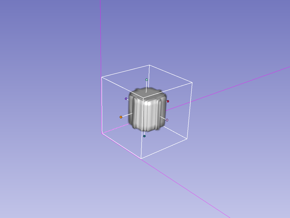
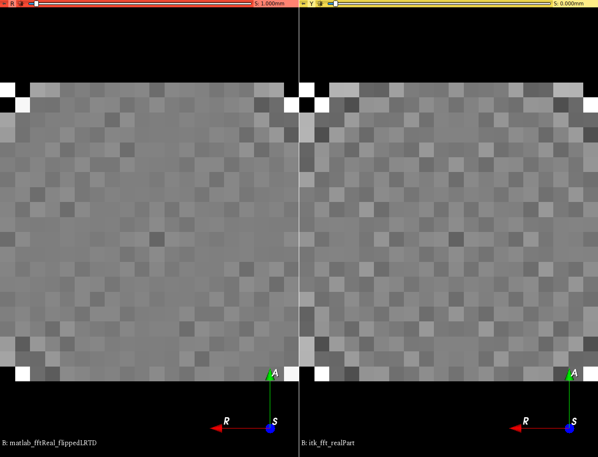
Here is the first slice visualization on slicer of the real part image after FFT with automatic range for grey level. imaginary parts are also different.
Thanks for providing more details to reproduce it.
Please post the minimal set of matlab commands you are using to read the image, apply the fftn, and write the output image, with the switch of axis you commented.
The output image generated by a fft has positive and negative frequencies, and also Nyquist frequencies depending on the oddness in size of the axis, so after switching of axis, the output has to be interpreted with care.
Last information that might be useful, ITK transformation matrix (displayed by slicer in the volume module) is [-1 0 0; 0 -1 0; 0 0 1]. The matlab transformation matrix generated before the flip is [1 0 0; 0 1 0; 0 0 1].
I don’t know what kind of transformation that plugin is doing with the function load_nii, but it doesn’t seem right, some comments in that plugin page seems to share this opinion.
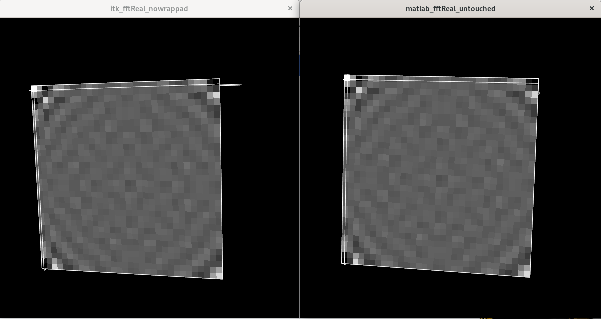
You get the same results in ITK and Matlab if you use the load_untouch_nii function instead, which seems to not perform any extra magic.
Also, I don’t think you are using the WrapPadImageFilter in your itk script correctly. Use the itkFFTPadImageFilter instead.
I have used no pad filter (to match your matlab usage of fftn) and both, the VNL fft and the FFTW fft in ITK, with same results.
I am sure it is an issue in how that plugin is reading/wrtiting the image in matlab. Not in the ITK side.
I was working on making a C++ version of Optimally oriented flux. The algorithm provided by Benmansour http://insight-journal.org/browse/publication/885 had some weird artefacts that I couldn’t explain. It was probably my attempt at updating the filter from itk V.3 ish to 5.1 that introduced weird things (middle view of the image).
Following the original matlab implementation from Law, seems much better (left view). Thanks again for the help.
A last question, is there an ITK implementation of Bessels functions with float parameters ? VNL bessels implementation only have int parameters. I would like to avoid using Boost::math for this filter.
Corrected: Those are C++17 functions not C++11. ITK currently only requires C++11, but perhaps for your application C++17 as a requirement would be OK.