Express AffineTransform as single 4x4 matrix

I have an AffineTransform ITK object that I would like to use with other registration tools. To do so, I need to express the transform as a single 4x4 matrix in world-world terms - that is, incorporating all the Parameters, Centre of Rotation, Offset, Fixed Parameters etc. I know tools exist to do this - convert3d - but I cannot find the source code to see how they do it. Could someone tell me the sequence of multiplications I need to do? My attempts at reverse-engineering this seem to be missing out a final shift of some sort.

Thanks in anticipation.
Tom

I donā€™t think center of rotation is part of the 4x4 matrix. But you can convert AffineTransform into a 4x4 matrix which has an implicit center of rotation at [0,0,0]. You will need to account for shifting the center of rotation, and I guess you need to figure out the math. Possibly from this or this.

Hello @T_Kirk,

It is straightforward to move from the ITK centered transformations to the 4x4 matrix.
In ITK we have:
T(\mathbf{x}) = A(\mathbf{x}-\mathbf{c}) + \mathbf{t} + \mathbf{c}

ITK nomenclature:
Matrix: the matrix A
Center: the point \mathbf{c}
Translation: the vector \mathbf{t}
Offset: \mathbf{t} + \mathbf{c} - A\mathbf{c}

In the 4x4 matrix, the upper left matrix is A, the upper right 3x1 column is -Ac+t+c.

2 Likes

Wow Iā€™m grateful for this. I knew there would be a simple sequence of steps, I just couldnā€™t find the right combination.

I will code this up tomorrow and test it out. Iā€™ll then be putting a GitHub gist up (lots of other people have asked this question online, with very little success), and finally Iā€™ll incorporate it into a registration library Iā€™m working on and link to it here. Hopefully the next person who comes across this question is able to find your answer.

Thank you very much!
Tom

Hi @zivy,

Unfortunately there still seems to be a small offset, its very confusing.

This is the transform Iā€™m working with:

AffineTransform (0x7fe6f09b0170)
   Matrix: 
     0.999653 0.0144549 0.0220433 
     -0.0155293 0.99866 0.049376 
     -0.0213 -0.0497012 0.998537 
   Offset: [3.55111, 5.85214, -5.28451]
   Center: [-5.10695, 11.6622, 19.4729]
   Translation: [4.15071, 6.87731, -5.78384]
   Inverse: 
     0.999653 -0.0155293 -0.0213 
     0.0144549 0.99866 -0.0497012 
     0.0220433 0.049376 0.998537 
   Singular: 0

Iā€™ve run the following steps to derive the overall transform T(x):

```overall = np.eye(4)
A = np.array(trans.GetParameters()[:9]).reshape(3,3)
c = np.array(trans.GetFixedParameters())
t = np.array(trans.GetParameters()[9:])
overall[:3,:3] = A
overall[:3,3] = (-A @ c) + t + c ```

Which gives me the following matrix:
array([[ 0.99965251, 0.01445486, 0.02204332, 3.55111468],
[-0.01552929, 0.99865953, 0.049376 , 5.85214032],
[-0.02130005, -0.04970116, 0.99853698, -5.28450612],
[ 0. , 0. , 0. , 1. ]])

Note that the final column does indeed match up to the offset for the transform, so thereā€™s a sanity check on the maths there.

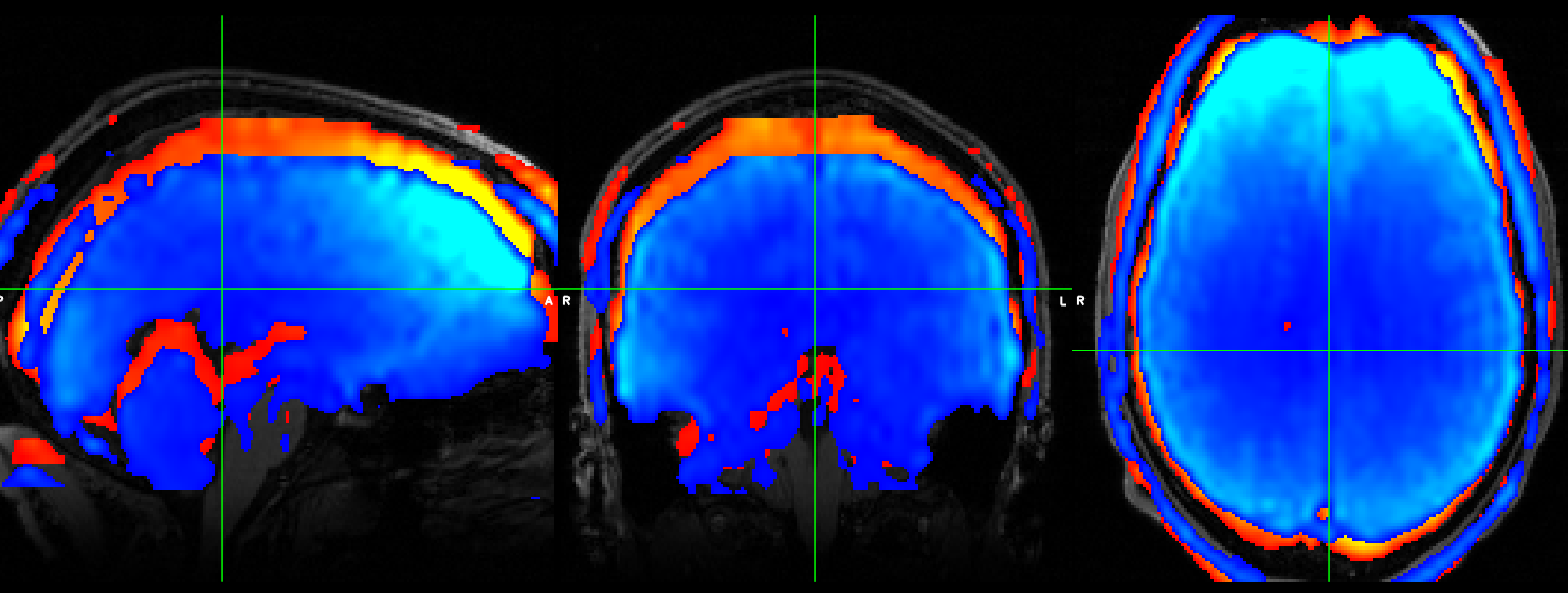
The confusing thing is that there is still some offset between using this matrix and the ground truth Iā€™m working with (an ANTs registered image). The ground truth is in red, the result of using my matrix is in blue, and there is clearly a shift in -z (and also smaller ones in x,y).

Any idea whats happening? It could well be that ANTs is doing something funny internally, and not using all of the parts of the transform (which I realise is an ANTs question, but so far they have been super unhelpful and told me this was an ITK questionā€¦)

Tom

Hello @T_Kirk,

This is all but impossible to debug when combined with the visualization component. Debugging requires that you limit the evaluation to the creation of the numpy matrix, visualization can include other bugs. Below is code using SimpleITK that illustrates that the conversion given above is valid (all the Get methods exist in ITK too so minimal change to code):

import SimpleITK as sitk
import numpy as np

tx = sitk.AffineTransform(3)
tx.SetMatrix([0.999653, 0.0144549, 0.0220433, 
             -0.0155293, 0.99866, 0.049376, 
             -0.0213, -0.0497012, 0.998537] )
tx.SetCenter([-5.10695, 11.6622, 19.4729])
tx.SetTranslation([4.15071, 6.87731, -5.78384])

A = np.array(tx.GetMatrix()).reshape(3,3)
c = np.array(tx.GetCenter())
t = np.array(tx.GetTranslation())
overall = np.eye(4)
overall[0:3,0:3] = A
overall[0:3,3] = -np.dot(A,c)+t+c

pnt = [10,3,4]

print(tx.TransformPoint(pnt))
print(np.dot(overall,pnt+[1]))
1 Like

Hi @zivy

Good point, I am aware that visual inspection can introduce small errors. However both images were drawn within the same voxel grid so Iā€™m confident what Iā€™m seeing is a genuine difference, not a display artefact.

Your code has got me thinking about something - it could be a zero-indexing error. The registration library I use assumes all images map into world space via a zero-indexed voxel to world matrix, not one-indexed (as is the case with MATLAB, for example). I think Iā€™m seeing a constant offset between my copy and ground truth, so a zero-indexing shift would make sense. Iā€™ll have a go and let you know.

Tom

Alas its not that. I tried shifting the zero-index (adding / subtracting multiples of the A.c + t + c offset) but its not corrected the problem.

Am I interpreting the coordinate system in right way? The overall step of operations I need to do in order to transform my image are as follows:

  1. generate a grid of reference voxel coordinates (the output space, zero-indexed)
  2. transform the grid into world-mm coordinates (using the voxel-world matrix of the reference space)
  3. apply the transformation - which requires the matrix to be in world-world terms (other tools, for example FSL, do not use this convention, hence why I am wondering if this is the problem)
  4. transform the voxel grid into source voxel coordinates (ie, the image that needs to be transformed onto the reference)
  5. interpolate onto the grid (using scipy map_coordinates)

I have an entire registration library set up already that is able to do all of these steps correctly for other registration frameworks (eg FSL). Internally, it converts all transforms into world-world terms before applying them. So, if I have understood correctly, all I need to do in order to use an ITK transform instead is step (3): I have code for all the other steps and donā€™t see why I would need to change that?

Hi @T_Kirk,
Sounds reasonable (though without looking at the code you never know).

The only common thing that goes wrong is in the ā€œgenerate grid of reference voxel coordinatesā€. Most of the time people assume that the spacing is the only thing needed, but if the direction cosine matrix of the image is not the identity the grid you are creating will be off as it follows the standard basis vectors and not the correct ones (e.g. gantry tilt from CT).

Hi T_kirk!
I saw your colored 3D model DICOM image, can you tell me how can i got this resultļ¼ˆeffectļ¼‰
thanks!

@zivy: good point, but I know in this case its an isotropic voxel grid (brain MRI). Hopefully I make some more progress later today

@wulicheng: Iā€™m using a viewer called FSLeyes (https://fsl.fmrib.ox.ac.uk/fsl/fslwiki/FSLeyes), which lets you set different colormaps for each image that you load in. I donā€™t think it can do DICOM however, these images are NIFTI

thanks!

If you use the latest SimpleITK binaries, there is a Python specific method Transform::Downcast, which will cast your transform to the proper derived class (AffineTransfrom). After that is done, you can update you from from trans.GetFixedParameters()->trans.GetCenter() and trans.GetParameters()[9:]->trans.GetTranslation() this change will clean up the code and and ensure correctness and clarity.

Another detail which may be related to this is the order of indexes in ITK vs NumPy. in SimpleITK/ITK the points are [ x, y, z ] like the itk::Point class and indexes are [ i, j ,k ] like the itk::Index and itk::ContinuousIndex classes, where i is the fast axes. While in numpy arrays are index as array[k,j,i] like a C array carray[k][j][i] and i is the fast axis or row. (Yes, some attributes in a numpy array can change this, but this is the convention. )

Thanks for this information @blowekamp, itā€™s very useful and could certainly matter for my application.

Regarding the first part of your answer, I agree that the code is simpler, however have I understood that your suggestions are purely for clarity and shouldnā€™t make a difference to the results?

Regarding the second part, I was not aware of this and and Iā€™m not sure what the implications could be. If it is the case that the matrix Iā€™m getting has the axes order flipped, would it be correct to transpose the upper left 3x3 matrix and flip the order of the upper right 1x3 column to compensate?

Hi all,

I think Iā€™ve worked it out. Its quite a sneaky little quirk that I suspect is related to the different conventions used to represent coordinates within image files.

I reduced my test case to registration via translation only. Using the last 3 Parameters of the transform (the translation vector), I then was able to reproduce the equivalent 4x4 affine matrix as follows:

overall = np.eye(4)

# The translation vector from the transform 
t = np.array(trans.GetParameters()[9:])

# Apply the translation in the last column of the 4x4 matrix 
overall[:3,3] = t 

# And then flip the sign of the z-component of translation (so add 2* -ve)
overall[2,3] += (2 * -t[2])

So the key step was to flip the sign on the z-component of the translation. Does anyone know what is going on here?

My initial guess would be that NIFTI images have z-coordinates that count upwards from the bottom of the data array and perhaps this is different to the other formats used by people on this forum, hence this detail slipped us by. Do let me know if you have another explanation!

Thanks to everyone that chipped in with helpful suggestions, I really appreciate it (and am pleasantly surprised by how responsive this forum is, you guys are a top community).

That really stinks of RAS/LPS discrepancy. ITK is using DICOMā€™s physical space convention: assuming identity direction matrix, I index increases from right to left, J index increases from anterior to posterior, and K index increased from inferior to superior.

Alas Iā€™m still baffled about how to make the rotation part of the matrix work.

I am using a pair of ā€˜flipā€™ matrices to map between LPS and RAS space (they are 1 1 -1 1 on the diagonal), and am able to make a simple example with pure translation work nicely:

trans = np.eye(4)
trans[:3,3] = translation 
overall = flip @ trans @ flip

I can also make a simple example with translation and rotation around the centre point work nicely (I generate the transform using c3d_affine_tool -trans -rot and then build the equivalent affine using various calls, as outlined in previous posts). Crucially, the centre of rotation for this transform is 0,0,0 according to simpleITK

trans = np.eye(4)
trans[:3,3] = translation 
trans[:3,:3] = rotation 
overall = flip @ trans @ flip

The problems start when I use a transform produced by ANTs. The centre of rotation is non-zero, and its this that goes wrong. I have tried calculating the offset (-A @ c + c + t) as outline previously, but this doesnā€™t solve the problem and I am fairly confident is the rotation part of the affine that is the root cause.

I am starting to despairā€¦