I have a question regarding the extra control points that gets added to the grid for the B-spline transformation.
I fully understand the one control point that gets added to the lower bound, but I don’t get why two control points gets added to the upper bound of the grid? I expected to see only one control points get added to the upper bound too.
Let me explain more:
we have (from paper 1 and paper2)
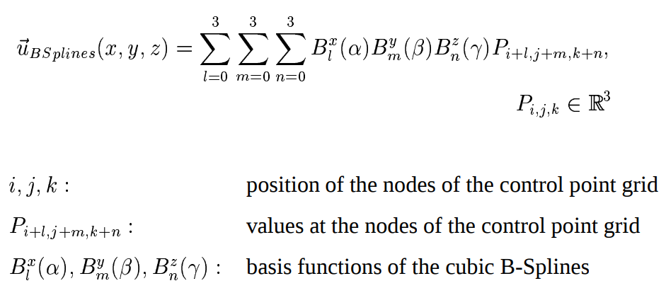
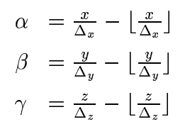
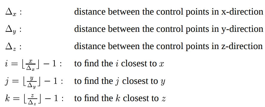
Let’s assume a 2D scenario (so no k index) in which we have couple of sampling points (the blue dots).
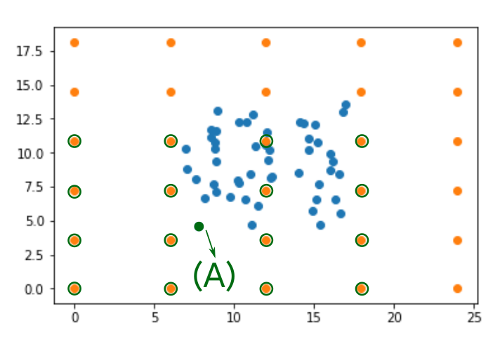
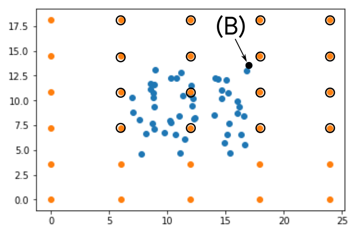
Based on the formula above the support control points (i,j indexes) are circled for Sample (A) and Sample (B). In both cases there is no need for the 2 added control points to the upper bound of the space. Only with 1 extra rows (added to the top and right hand side) the support can be achieved.
Am i missing something? Why does ITK add two extra control points to the upper bound instead of just 1 ?
I’m seeing the 3D slicer tutorial/documentation that only 1 row/column is added
https://www.slicer.org/wiki/Documentation/4.10/FAQ#What.27s_the_BSpline_Grid_Size.3F