One last thing, then I will stop polluting this thread.  Previously, I’d been using
 vtkImagePlaneWidget to scroll through my images. However, this widget seems to be restricted to viewing axis-aligned data, preventing me from using it to view slices through the (world-coordinate-aligned) volume rendered data. However, I was able to replicate the functionality pretty closely. Broadly, the steps were:
- Use
vtkPlaneWidget to select the plane (in world coordinates) you’d like to reslice.
- Tie this using a callback to a
vtkPlaneSource.
- Transform the
vtkPlaneSource data back into image space.
- Use
vtkProbeFilter to resample the image data according to the transformed vtkPlaneSource data.
- Transform the data back, and display it on top of the
vtkPlaneWidget.
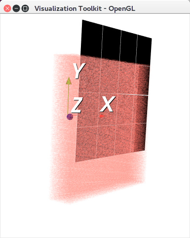
When you do this on to of a volume render, moving the vtkPlaneWidget around gives the effect of reslicing the image data underlying the volume render. I don’t know if this is the best or right way to approach this problem, but it works quite well for my purposes, so I thought I’d share the code in case anyone needs to do something similar.
Best,
–Davis
Screenshot:
Code:
// ITK
#include <itkImageFileReader.h>

// VTK
#include <vtkNIFTIImageReader.h>
#include <vtkPlaneSource.h>
#include <vtkProbeFilter.h>
#include <vtkLookupTable.h>
#include <vtkRenderer.h>
#include <vtkRenderWindow.h>
#include <vtkRenderWindowInteractor.h>
#include <vtkDataSetMapper.h>
#include <vtkProperty.h>
#include <vtkActor.h>
#include <vtkProperty.h>
#include <vtkPlaneWidget.h>
#include <vtkCommand.h>
#include <vtkMatrix4x4.h>
#include <vtkGPUVolumeRayCastMapper.h>
#include <vtkPiecewiseFunction.h>
#include <vtkVolumeProperty.h>
#include <vtkColorTransferFunction.h>
#include <vtkTransform.h>
#include <vtkTransformFilter.h>
#include <vtkAxesActor.h>
#include <vtkImageData.h>

/*
 Given an ITK image, use the origin and direction to create a vtkMatrix.
 This matrix can be used to construct a vtkTransform, which will take data in image coordinates
 and transform them into world coordinates.
 */
template<typename TImage>
void
GetVTKTransformationMatrixFromITKImage(const typename TImage::Pointer image, vtkMatrix4x4* mat)
{
  // Direction Matrix
  typename TImage::DirectionType d = image->GetDirection();
  for (int i=0; i<3; ++i)
    {
    for (int j=0; j<3; ++j)
      {
      mat->SetElement(i, j, d(i,j));
      }
    }

  // Origin
  typename TImage::PointType o = image->GetOrigin();
  for (int i=0; i<3; ++i)
    {
    mat->SetElement(i, 3, o[i]);
    }
}

/*
 Get a sensible origin, point1, and point2 (in world coordinates) to initialize
 the vtkPlaneWidget, which is used to control which cross section of the data is viewed.
 */
template<typename TImage>
void
GetPointsFromITKImage(const typename TImage::Pointer image,
                      typename TImage::PointType &o,
                      typename TImage::PointType &p1,
                      typename TImage::PointType &p2)
{
  const typename TImage::SizeType size = image->GetLargestPossibleRegion().GetSize();
  const typename TImage::IndexType index = image->GetLargestPossibleRegion().GetIndex();

  auto o_index = index;
  o_index[2] += size[2] / 2;

  auto p1_index = index;
  p1_index[2] += size[2] / 2;
  p1_index[0] += size[0];

  auto p2_index = index;
  p2_index[1] += size[1];
  p2_index[2] += size[2] / 2;

  image->TransformIndexToPhysicalPoint(o_index, o);
  image->TransformIndexToPhysicalPoint(p1_index, p1);
  image->TransformIndexToPhysicalPoint(p2_index, p2);
}

/*
 A callback function which keeps the position of a vtkPlaneSource
 in sync with a vtkPlaneWidget.
 */
class PlaneWidgetCallback: public vtkCommand
{
public:
static PlaneWidgetCallback *New()
{
  return new PlaneWidgetCallback;
}

void Execute(vtkObject*, unsigned long, void*) override
{
  this->source->SetOrigin(this->widget->GetOrigin());
  this->source->SetPoint1(this->widget->GetPoint1());
  this->source->SetPoint2(this->widget->GetPoint2());
}

vtkPlaneWidget* widget;
vtkPlaneSource* source;

};

// Standard ITK typedefs.
typedef itk::Image<short, 3> TImage;
typedef itk::ImageFileReader< TImage > TReader;

int
main (int argc, char **argv)
{

  if (argc != 2)
    {
    std::cerr << "Usage: " << argv[0] << " ./path/to/image.nii" << std::endl;
    return EXIT_FAILURE;
    }

  const std::string fileName(argv[1]);

  //
  // The ITK image reader is preserves the image's origin and direction.
  // Using this data, vtkTransforms are constructed which can transform
  // `forward` (i.e., from image coordinates to world coordinates) and
  // `backward` (i.e., from world coordinates to image coordinates).
  //

  TReader::Pointer itkReader = TReader::New();
  itkReader->SetFileName( fileName );
  itkReader->Update();

  const vtkSmartPointer<vtkMatrix4x4> fMat = vtkSmartPointer<vtkMatrix4x4>::New(); // forward
  const vtkSmartPointer<vtkMatrix4x4> bMat = vtkSmartPointer<vtkMatrix4x4>::New(); // backward

  GetVTKTransformationMatrixFromITKImage<TImage>( itkReader->GetOutput(), fMat);

  vtkSmartPointer<vtkTransform> fTrans = vtkSmartPointer<vtkTransform>::New();
  vtkSmartPointer<vtkTransform> bTrans = vtkSmartPointer<vtkTransform>::New();

  fTrans->SetMatrix( fMat );
  fTrans->GetInverse( bMat );
  bTrans->SetMatrix( bMat );

  // Get sensible points to initialize the vtkPlaneWidget.
  TImage::PointType origin, point1, point2;

  GetPointsFromITKImage<TImage>(itkReader->GetOutput(), origin, point1, point2);

  //
  // Create renderer, render window, and render window interactor.
  //

  vtkSmartPointer<vtkRenderer> renderer =
    vtkSmartPointer<vtkRenderer>::New();
  vtkSmartPointer<vtkRenderWindow> window =
    vtkSmartPointer<vtkRenderWindow>::New();
  window->AddRenderer(renderer);
  vtkSmartPointer<vtkRenderWindowInteractor> interactor =
    vtkSmartPointer<vtkRenderWindowInteractor>::New();
  interactor->SetRenderWindow(window);

  //
  // Read Image.
  // Note that, unlike itk::ImageFileReaders, vtk*ImageReaders do not
  // preserve origin or direction information.
  //

  vtkSmartPointer<vtkNIFTIImageReader> vtkReader =
    vtkSmartPointer<vtkNIFTIImageReader>::New();
  vtkReader->SetFileName( fileName.c_str() );
  vtkReader->Update();

  std::cout << vtkReader->GetOutput()->GetOrigin()[0] << ' '
            << vtkReader->GetOutput()->GetOrigin()[1] << ' '
            << vtkReader->GetOutput()->GetOrigin()[2] << std::endl;

  //
  // Render the volume, putting the volume into proper world coordinates.
  //

  // 200 to 700 is approximately the range of hounsfield units for
  // contrast enhansement in the cardiac bloodpool; we set alpha to be
  // zero outside of this range and 0.05 within.
  // Change these values to reflect the intensity range of the structure you
  // would like to highlight.
  vtkSmartPointer<vtkPiecewiseFunction> compositeOpacity =
  vtkSmartPointer<vtkPiecewiseFunction>::New();
  compositeOpacity->AddPoint(199.0,0.0);
  compositeOpacity->AddPoint(200.0,0.05);
  compositeOpacity->AddPoint(700.0,0.05);
  compositeOpacity->AddPoint(701.0,0.0);

  // Some arbitrary color gradient.
  vtkSmartPointer<vtkColorTransferFunction> color =
  vtkSmartPointer<vtkColorTransferFunction>::New();
  color->AddRGBPoint(200.0,1.0,0.5,0.5);
  color->AddRGBPoint(700.0,5.0,1.5,0.5);

  // Add to opacity and color gradient to a volume property.
  vtkSmartPointer<vtkVolumeProperty> volumeProperty =
  vtkSmartPointer<vtkVolumeProperty>::New();
  volumeProperty->SetScalarOpacity(compositeOpacity);
  volumeProperty->SetColor(color);

  // Create a volume mapper.
  vtkSmartPointer<vtkGPUVolumeRayCastMapper> volumeMapper =
    vtkSmartPointer<vtkGPUVolumeRayCastMapper>::New();
  volumeMapper->SetInputConnection( vtkReader->GetOutputPort() );

  // Create a volume, and add both the mapper and volume property.
  vtkSmartPointer<vtkVolume> volume =
    vtkSmartPointer<vtkVolume>::New();
  volume->SetMapper(volumeMapper);
  volume->SetProperty(volumeProperty);

  // Important!!
  // Set the user matrix to fMat (the forward transformation matrix
  // calculated from the ITK image).
  volume->SetUserMatrix(fMat);

  //
  // Image Plane, Oriented in World Coordinates
  //

  // vtkPlaneWidget has user interaction baked in; this will be used
  // to allow the user to select which slice to view.
  vtkSmartPointer<vtkPlaneWidget> plane =
    vtkSmartPointer<vtkPlaneWidget>::New();

  // Initialize the widget position with the origin, point1, and point2 from above.
  plane->SetInteractor(interactor);
  plane->SetOrigin(origin.GetVnlVector().data_block());
  plane->SetPoint1(point1.GetVnlVector().data_block());
  plane->SetPoint2(point2.GetVnlVector().data_block());
  plane->On();

  // Define a model for the "image". Its geometry matches the implicit
  // sphere used to clip the isosurface
  vtkSmartPointer<vtkPlaneSource> planeSource =
    vtkSmartPointer<vtkPlaneSource>::New();
  planeSource->SetOrigin(origin.GetVnlVector().data_block());
  planeSource->SetPoint1(point1.GetVnlVector().data_block());
  planeSource->SetPoint2(point2.GetVnlVector().data_block());
  planeSource->SetResolution(128, 128); // Good compromise between detail and performance.

  // This callback will update the plane source, keeping its position in sync
  // with the widget.
  vtkSmartPointer<PlaneWidgetCallback> callback =
    vtkSmartPointer<PlaneWidgetCallback>::New();
  callback->widget = plane;
  callback->source = planeSource;
  plane->AddObserver( vtkCommand::InteractionEvent, callback );

  // Transform the plane souce back into image coordinates.
  vtkSmartPointer<vtkTransformFilter> bTransFilter =
    vtkSmartPointer<vtkTransformFilter>::New();
  bTransFilter->SetTransform( bTrans );
  bTransFilter->SetInputConnection( planeSource->GetOutputPort() );

  // vtkProbeFilter will sample the values of the image data at the polydata positions.
  vtkSmartPointer<vtkProbeFilter> probe =
    vtkSmartPointer<vtkProbeFilter>::New();
  probe->SetInputConnection( bTransFilter->GetOutputPort() );
  probe->SetSourceConnection( vtkReader->GetOutputPort() );
  probe->Update();

  // Transform the sampled data back into world coordinates.
  vtkSmartPointer<vtkTransformFilter> fTransFilter =
    vtkSmartPointer<vtkTransformFilter>::New();
  fTransFilter->SetTransform( fTrans );
  fTransFilter->SetInputConnection( probe->GetOutputPort() );

  // Define a suitable grayscale lut
  vtkSmartPointer<vtkLookupTable> bwLut =
    vtkSmartPointer<vtkLookupTable>::New();
  bwLut->SetTableRange(-1024, 2048);
  bwLut->SetSaturationRange(0, 0);
  bwLut->SetHueRange(0, 0);
  bwLut->SetValueRange (.2, 1);
  bwLut->Build();

  // Create a mapper for the sampled image data.
  vtkSmartPointer<vtkDataSetMapper> imageSliceMapper =
    vtkSmartPointer<vtkDataSetMapper>::New();
  imageSliceMapper->SetInputConnection( fTransFilter->GetOutputPort());
  imageSliceMapper->SetScalarRange(-1024, 2048);
  imageSliceMapper->SetLookupTable(bwLut);

  vtkSmartPointer<vtkActor> image =
    vtkSmartPointer<vtkActor>::New();
  image->SetMapper(imageSliceMapper);

  //
  // Add coordinate system axes, so we have a reference for position and orientation.
  //

  vtkSmartPointer<vtkAxesActor> axes = vtkSmartPointer<vtkAxesActor>::New();
  axes->SetTotalLength(100,100,100);
  axes->SetShaftTypeToCylinder();
  axes->SetCylinderRadius(0.01);

  //
  // Put it all together.
  //

  // Set the background color
  renderer->SetBackground(1.0, 1.0, 1.0);

  // Add actors and volume.
  renderer->AddActor( axes );
  renderer->AddActor( image );
  renderer->AddVolume( volume );

  // Set a background color for the renderer and set the size of the
  // render window (expressed in pixels).
  window->SetSize(640, 480);

  // Initialize the event loop and then start it.
  interactor->Initialize();
  interactor->Start();

  return EXIT_SUCCESS;
}
[1] https://itk.org/Wiki/ITK/Examples/IO/itkVtkImageConvertDICOM