Inverting Resample Filter Execute operation

Hello,

The problem that I am trying to solve with SimpleITK:
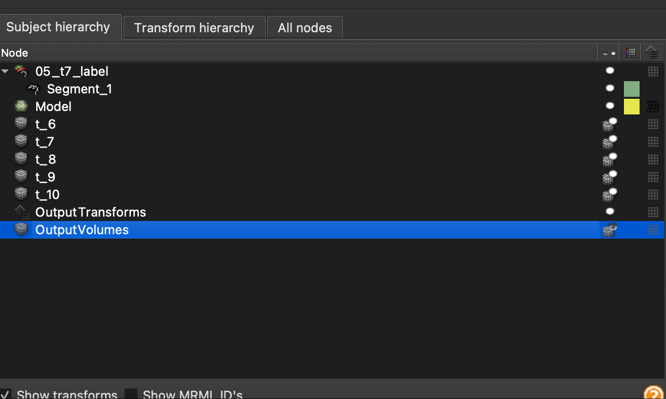
1/ I have a temporal sequence of volumes from the same patient
2/ I have one segmentation mask of the organ under observation.
3/ I want to get segmentations based on registration and transforms from the one mask for all the temporal sequences:
4/ Apply that for meshes

I first obtain the deformation fields and then warp the mask with the displacement field for all the volumes in the temporal sequence. Therefore I gain the segmentations for all volumes.

Vref = sitk.ReadImage(original_mask)
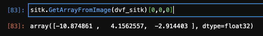
dvf_sitk = sitk.ReadImage(deformation_field_path)
resampler = sitk.ResampleImageFilter()
resampler.SetReferenceImage(Vref)
dis_tx = sitk.DisplacementFieldTransform(sitk.Cast(dvf_sitk,sitk.sitkVectorFloat64))
resampler.SetTransform(dis_tx)
out = resampler.Execute(Vref)

However, I want to work with meshes. For the first segmented volume I applied Delaunay surface triangulation to obtain the mesh. Then, I’d like to change the mesh based on the deformation field (therefore not changing the adjacency matrix and cardinality of the set of nodes).

I thought about using the displacementfield, however they yield float values.

np.unique(sitk.GetArrayFromImage(dvf_sitk))
array([-33.68408 , -33.51517 , -33.3977  , ...,  19.781471,  19.782059, 19.919436], dtype=float32)

The documentation for ResampleImageFilter / WarpImageFilter states:

Note that the choice of interpolator function can be important. This function is set via SetInterpolator() . The default is LinearInterpolateImageFunction <InputImageType, TInterpolatorPrecisionType>, which is reasonable for ordinary medical images. However, some synthetic images have pixels drawn from a finite prescribed set.

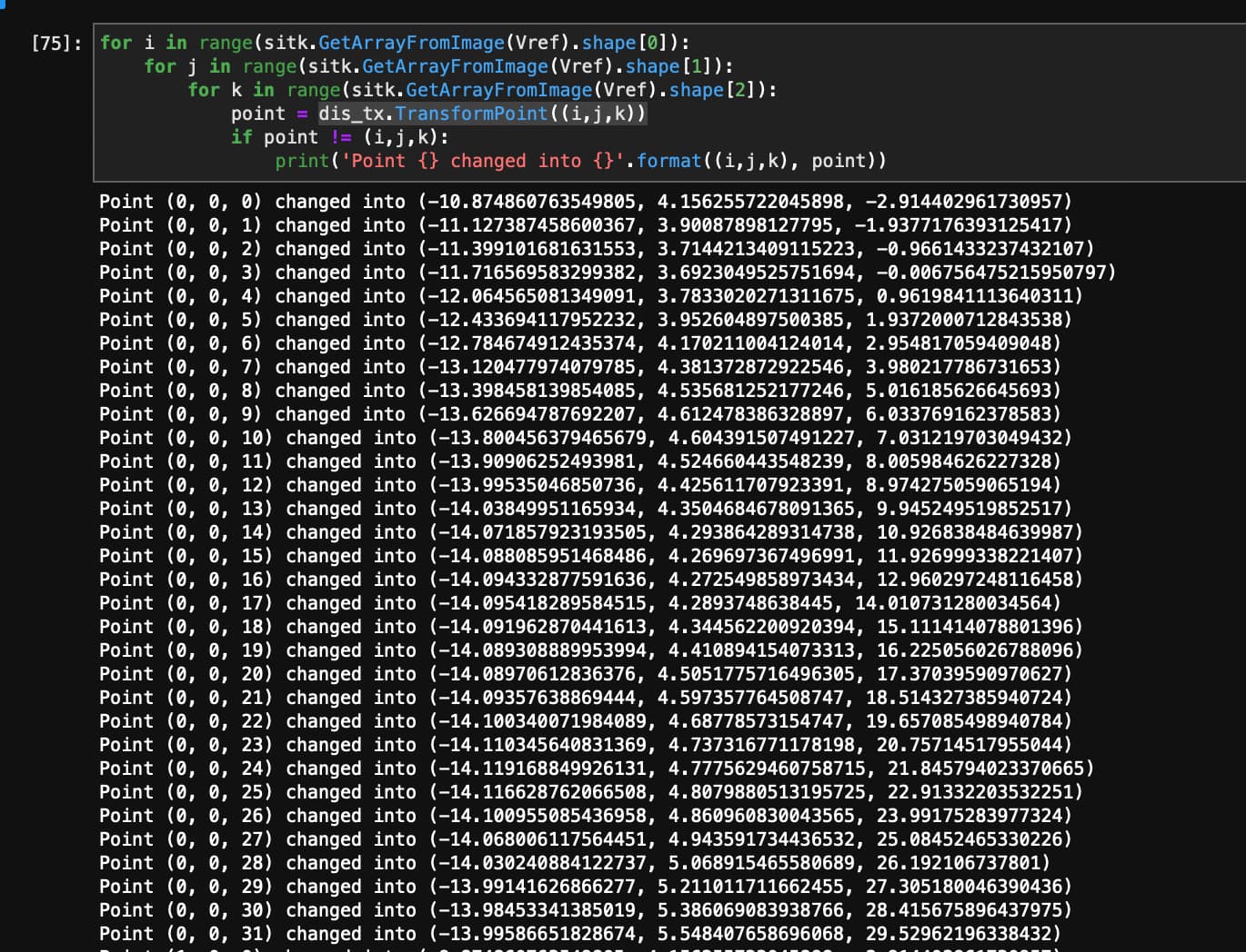
So, the warping after using the values from displacementfield interpolates the float numbers into integers. Since I want to work with mesh, how can I get the mappings how each point changed?

For instance, voxel [3,5,7] after resampling can be found at [3,5,8] etc.

Thanks!

You should probably use DisplacementFieldTransform, and apply its TransformPoint method to all points in your mesh. That will only affect positions of vertices, and retain topology information.

Thank you for your answer. I tried to use transformpoint, however it still yields float values, see either image or the code excerpt:

I think we should achieve to have integer values, right?

Point (0, 0, 0) changed into (-10.874860763549805, 4.156255722045898, -2.914402961730957)
Point (0, 0, 1) changed into (-11.127387458600367, 3.90087898127795, -1.9377176393125417)
Point (0, 0, 2) changed into (-11.399101681631553, 3.7144213409115223, -0.9661433237432107)
Point (0, 0, 3) changed into (-11.716569583299382, 3.6923049525751694, -0.006756475215950797)
Point (0, 0, 4) changed into (-12.064565081349091, 3.7833020271311675, 0.9619841113640311)
Point (0, 0, 5) changed into (-12.433694117952232, 3.952604897500385, 1.9372000712843538)
Point (0, 0, 6) changed into (-12.784674912435374, 4.170211004124014, 2.954817059409048)
Point (0, 0, 7) changed into (-13.120477974079785, 4.381372872922546, 3.980217786731653)
Point (0, 0, 8) changed into (-13.398458139854085, 4.535681252177246, 5.016185626645693)
Point (0, 0, 9) changed into (-13.626694787692207, 4.612478386328897, 6.033769162378583)
Point (0, 0, 10) changed into (-13.800456379465679, 4.604391507491227, 7.031219703049432)
Point (0, 0, 11) changed into (-13.90906252493981, 4.524660443548239, 8.005984626227328)
Point (0, 0, 12) changed into (-13.99535046850736, 4.425611707923391, 8.974275059065194)

Each voxel of a deformation field contains the deformation vector, which says how much has that pixel needs to move. What you might be wanting is:

for ...
  oIndex = (i, j, k)
  dv = deformationField[oIndex]
  newIndex = oIndex + dv # might be minus instead of plus
  print("Index {oIndex} changed into {newIndex}")

of course, it’s the same as I did, please see following output:

sitk.GetArrayFromImage(dvf_sitk)[0,0,0]
array([-10.874861 ,   4.1562557,  -2.914403 ], dtype=float32)

The deformation field has a deformation vector consisting of float values, not the integer ones (you can see that in the original post). I suspect that warping uses additional interpolation, which I cannot get my hands on, therefore I don’t know how to make integer values out of the float values in the deformation vectors.

You might be going the wrong way. Take moving image indices, add (or subtract?) deformation vectors to them and you will get your fixed image indices. Those fractional indices are used for interpolation. You can round them to integer values, if you want integers.

But I still don’t know why you want integers, if you want to apply it to meshes? Mesh vertices have float coordinates.

Hello @BraveDistribution,

When working with a transformation you are always mapping physical points. The resampling code does this under the hood, converts voxel indexes to physical points and maps those to the image we want to resample. Finally, the intensity value at the non-grid location is computed via interpolation.

The conventions that you need to be familiar with:

  1. Transformation obtained via SimpleITK/ITK registration: maps points from the fixed image coordinate system to the moving image coordinate system.
  2. Resampling is done using an inverse-mapping approach. Iterate over the input grid, possibly defined by an image, and map those points to locations on the image we want to resample.
  3. When mapping surface/contour points we usually want to use direct-mapping.

In your case:

I1, S1, M1 - I1, image1, has an associated segmentation mask S1 and mesh M1.
I2 - second image.

If we want to map S1 onto I2:

  1. T = register(fixed_image=I2, moving_image=I1)
  2. S2 = resample(image1=S1, referenceImage=I2, transform=T, interpolator=sitkNearestNeighbor)

To map M1 onto I2 we need to use the inverse of the transformation T above.

If all we want is to map M1 onto I2, then switch the roll of fixed and moving images above and use the transform T to map the mesh points M2=T(M1).

If you need to map both the segmentation mask S1 and the mesh M1, then:

  1. Compute T as above.
  2. S2 = resample(image1=S1, referenceImage=I2, transform=T, interpolator=sitkNearestNeighbor)
  3. M2 = inverse(T)(M1) (see this Jupyter notebook for details on how to invert the displacement field transform).

Dear @zivy,

thank you for this wonderful explanation. I can find resample in sitk api reference, but I don’t see any “register” function there. Would you be so kind to elaborate a bit more?

Shall I use instead of the register function something like sitk.ElastixImageFilter()? So far, to get the segmentations I had this code. Shall I just append “3” from your comment?

  1. M2 = iverse(T)(M1) (see this Jupyter notebook for details on how to invert the displacement field transform).
img1 = "t_12.nii.gz"
segm1 = "t12_label.nii"
mesh = ""
img2 = "t_15.nii.gz"
transforms_rigid = "/store/matej/elastix_scripts/Par0057Bspline.txt"
transforms_deform = "/store/matej/elastix_scripts/Par0057Rigid.txt"

elastixImageFilter = sitk.ElastixImageFilter()
elastixImageFilter.SetFixedImage(sitk.ReadImage(img2))
elastixImageFilter.SetMovingImage(sitk.ReadImage(img1))
parameterMap1 = sitk.ReadParameterFile(transforms_rigid)
parameterMap2 = sitk.ReadParameterFile(transforms_deform)
elastixImageFilter.SetParameterMap(parameterMap1)
elastixImageFilter.AddParameterMap(parameterMap2)
elastixImageFilter.Execute()

transformixImageFilter = sitk.TransformixImageFilter()
transformParameterMap = elastixImageFilter.GetTransformParameterMap()
transformixImageFilter.SetTransformParameterMap(transformParameterMap)
transformixImageFilter.ComputeDeformationFieldOn()
transformixImageFilter.SetMovingImage(sitk.ReadImage(img2_mask))
transformixImageFilter.Execute()
deformationField = transformixImageFilter.GetDeformationField()

thanks.

Hello @BraveDistribution,

Two things: First, what I wrote was pseudo-code, so it’s just general step descriptions (no real code). Second, you aren’t actually using SimpleITK. You are using SimpleElastix. That toolkit extended SimpleITK / built on SimpleITK but, unfortunately, the name wasn’t changed.

I don’t think SimpleElastix implemented the filters that invert a deformation field so you’ll have to select the moving and fixed images so that you get the transformation in the direction you need.

Thank you @Zivy again.

Yes, I know that I use SimpleElastix since I had the transformation files for the registration. I thought they can be used interchangeably.

I don’t think SimpleElastix implemented the filters that invert a deformation field so you’ll have to select the moving and fixed images so that you get the transformation in the direction you need.

Can I do that in current settings? Is it easier to do everything from scratch in simpleitk instead of simpleelastix? Or shall I continue with SimpleElastix?

Thanks!

Hello @BraveDistribution,

Before you change anything, do a lazy evaluation (minimize the work you need to do):

  1. Do you really need the transformations in both directions. If not, select the fixed and moving images to yield the transformation you need. [no change to existing code]
  2. Check if any of the deformation field inversion options are available in SimpleElastix (InvertDisplacementFieldImageFilter,
    InverseDisplacementFieldImageFilter,
    IterativeInverseDisplacementFieldImageFilter). [one line change to existing code]
  3. If filters not available, if time is not an issue, run the registration in both directions. Just a one liner if the registration code is defined in a function (t1=register(a,b), t1_inverse=register(b,a)). Note that this will not be an exact inverse as there is no constraint enforcing it. [one line change to existing code]
  4. Recode using SimpleITK. [significant changes to existing code]

Hope this helps.

1 Like

Hello @zivy,

thank you for the answer. I am starting to understand how this should work and I’ll try to share my algorithm afterwards.

From SimpleElastix webpage https://simpleelastix.readthedocs.io/PointBasedRegistration.html:

If we want to warp points from the moving image to fixed image, we need the inverse transform. This can be computed manually (see section 6.1.6 in the elastix manual) or via `elastixImageFilter.ExecuteInverse()

It seems like they support the inverse transforms.

I think that 1/ will be enough, however now I need to solve the problem of transforming the mesh structure. Right now, I don’t know how we can apply transforms in sitk nor simpleelastix on meshes (in .vtk) format.

I think that your first approach can be done in 3D Slicer as well with the following steps:
1/ Load I1, I2
2/ Load S1
3/ Register image via SlicerElastix, set moving image to I2 and fixed image to I1, get transform T
4/ Create a mesh structure via SegmentMesher (using Cleaver2)
5/ Apply T to output from 4

Right now I think I’ll try to apply transform on point set (Point-based Registation — SimpleElastix 0.1 documentation), but first I need to change the .vtk unstructuredgrid to .VTK pointdata legacy format, which is the only format supported by SimpleElastix.
` .

EDIT: ExecuteInverse was disabled, see How to use elastixImageFilter.ExecuteInverse()? · Issue #278 · SuperElastix/SimpleElastix · GitHub

This whole workflow is implemented already in 3D Slicer’s Sequence Registration extension: you just need to provide an input image sequence and select a parameter set for Elastix. The extension performs pairwise registration of a selected frame (e.g., the frame that you segmented) in either resampling or modeling direction. The computed sequence of displacement fields can be used to transform images, segmentations, meshes, markups, etc. the inverse transform is automatically computed dynamically (e.g., for transforming a model you don’t need to compute an entire inverse transform, only find the inverse at vertex positions).

Short video tutorial:

3D Slicer can also visualize transforms (and images, meshes, etc.) in slice and 3D views, invert, convert transforms, all with using GUI, Python console, or Jupyter notebook. These should all help develop a full understanding of how things work. You also get GUI for testing multiple registration toolkits - Elastix, ANTs, and BRAINS.

1 Like

Thank you @lassoan for the answer. I downloaded the extension and now I quite understand how it works.

So I have a volumetric mesh sequence here:

Is there a possibility how to export the temporal volumetric mesh where I can see how each voxel moves? Ultimately, I want to represenet that mesh as a graph with coordinates as the node features.

You can copy-paste this code snippet into the Slicer Python console to export a mesh (.ply) file sequence from the warped segmentations: Script repository — 3D Slicer documentation

Dear @Lassoan,

thank you for your assistance.

I will share the full script in python somewhere as a gist for users that would like to follow the same approach as me.

Right now I have troubles how to apply the transform to the model (meshed segmentation) and save it.

My 3d slicer looks like this after the script was run:

After I apply OutputTransforms and run the sequence, it works fine and it changes as a gif:

The question is, how do I change the mesh from each step? Example script from Script repository — 3D Slicer documentation doesn’t work, since is a TransformNode which does not have

getNode(“OutputTransforms”).GetNumberOfDataNodes() functino
(MRMLCorePython.vtkMRMLTransformNode)0x18d5c4d08

thanks

It might make sense to continue this conversation on Slicer’s forum. Even if so, sharing a link to your final solution here would be welcome.

1 Like