Interpolate a given point from nifti DVF image volume

I have extracted a mesh points from a given nifti image which has a dimension of (203, 127, 161).
Additionally, I have a deformation vector field as an another nifti file which is generated using the aforementioned 3D nifti image using another tool. The shape of this DVF nifti mage is (203, 127, 161, 1, 3). Here the deformation field is the final position of the voxel after it has been transformed, i.e. it is the initial position of the voxel + the displacement of the voxel.

Now I need to interpolate a given point in physical space from this deformation vector field. How can I accomplish this ? Could you please give an example code ? For example I want to interpolate [717.89, 433. , -126.78] point which is in physical space from this DVF. How can I achieve this ?

I highly appreciate your willingness to help me out on this issue.

Hello @isuruwi,

I believe what you want is a modification of the Resampling at a set of locations section in this Jupyter notebook. The difference is in the definition of the displacement_img, which in your case should use the DVF nifti image to generate the physical_points instead of using the img.

Hi Ziv,

I don’t want to produce the physical points at all. In my situation, there is a set of mesh points in physical space, say the mesh points array shape is (700, 3), and I need to interpolate these points from the DVF image volume, which has the shape of (203, 127, 161, 1, 3).

Is it necessary to generate interp_grid_img variable as in the pointed code even if I have mesh point coordinates in physcal space?

Is it possible to pass mesh points (in physical space) into the sitk.Resample function? Is there something I’m missing or misunderstood?

I’m hoping you can assist me in resolving this problem. Thanks in advance for your time and consideration.

Hello @isuruwi,

I don’t think I understand what it is you want to do, but maybe I’m lucky. Here is my current understanding:

Given a physical point and displacement vector field, you want to apply the transformation defined by the displacement field to that point. Please see code:

import SimpleITK as sitk

image = sitk.ReadImage('training_001_ct.mha')
#image with vectors representing the spatial coordinates of the original image pixels
image_physical_points = sitk.PhysicalPointSource(outputPixelType = sitk.sitkVectorFloat64,
size = image.GetSize(),
origin = image.GetOrigin(),
spacing = image.GetSpacing(),
direction = image.GetDirection())

#adding constant value to the first coordinate of all points to get something similar to the
#DVF described above
new_first_component = sitk.VectorIndexSelectionCast(image_physical_points,0) + 1.2
dvf_image = sitk.Compose([new_first_component] + [sitk.VectorIndexSelectionCast(image_physical_points,i) for i in range(1,image.GetDimension())])

#create the SimpleITK representation of the DVF transformation, which differs from the dvf_image
sitk_dvf = sitk.DisplacementFieldTransform(dvf_image - image_physical_points)

# transform the point at voxel [0,0,1]
sitk_dvf.TransformPoint(image_physical_points[0,0,1])
# transform a point that is 0.5mm away from voxel one in x:
new_point = [image_physical_points[0,0,1][0] + 0.5,
image_physical_points[0,0,1][1],
image_physical_points[0,0,1][2]]
sitk.dvf.TransformPoint(new_point)
2 Likes

Hello @isuruwi,

What you are experiencing is due to a mismatch between coordinate systems. All of the points listed are outside the domain of the displacement field transformation (limited to the image region, outside of which it is the identity).

SimpleITK uses a LPS / DICOM based coordinate system and you are working with nifti. For additional details, please see general discussion of coordinate systems and a nifti specific paper. For the transformation to work as expected on the mesh points, you will need to modify them so that they use the DICOM coordinate system.

Code illustrating the situation:

import SimpleITK as sitk

image = sitk.ReadImage("MCR.nii.gz")
print("Physical image bounds:")
print(image.TransformIndexToPhysicalPoint([0,0,0]))
print(image.TransformIndexToPhysicalPoint([sz-1 for sz in image.GetSize()]))

image_physical_points = sitk.PhysicalPointSource(
    outputPixelType=sitk.sitkVectorFloat64,
    size=image.GetSize(),
    origin=image.GetOrigin(),
    spacing=image.GetSpacing(),
    direction=image.GetDirection(),
)
# read the DVF image and correct the coordinate system, from nifti to DICOM which is
# what SimpleITK uses, negate x and y, z remains the same.
dvf_image = sitk.ReadImage("change_0_DVF0000.nii.gz")
corrected_dvf_image = sitk.Compose(
    [
        -sitk.VectorIndexSelectionCast(dvf_image, 0, sitk.sitkFloat64),
        -sitk.VectorIndexSelectionCast(dvf_image, 1, sitk.sitkFloat64),
        sitk.VectorIndexSelectionCast(dvf_image, 2, sitk.sitkFloat64),
    ]
)

voxel_index = [10,10,10]
print("Original and transformed voxel locations:")
print(image_physical_points[voxel_index])
print(corrected_dvf_image[voxel_index])
1 Like

Hi Zivy,

Okay, I’ve resolved the conflict between coodinate systems. All of the mesh points are now within the domain of the displacement field transformation.

However, I believe the mesh points are incorrectly distorted after I applied the displacement field in accordance with the afoenetioend steps.

I’ve included 3D slcier views below for the reference 3D CT (MCR.nii.gz) and the corresponding reference 3D volumetric mesh.

The figure below displays the 3D slicer output after deforming the reference 3D mesh points according to the extracted dispalcement vector field from teh DVF image volume as the steps you explained before.

As an alternative to using this DVF image volume, I used deamons registration to extract the associated displacement field by transferring the reference 3D CT volume to the deformed 3D CT volume. Once I’ve extracted this, I’ll go through the same steps you detailed previously. The slicer view is depicted below.

Please see the red circles in the accompanying slicer views for further information. What may be the cause of this? Is the sitk dvf.TransformPoint() method capable of transforming a physical point based on its displacement vector field? Does it, in other words, offer the absolute location of the original physical point once this transformation is applied?

I’ve shared with you a reference CT (MCR.nii.gz), deformed CT volume (change_0_simDyn0009.nii.gz) and corresponding DVF image volume (change_0_DVF0009.nii.gz) and the reference volumetric mesh (i.e. a .vtk file) for your further reference. (via google drive)
https://drive.google.com/drive/folders/1qSZtw6Bp3xsmSDTwZ9tcl6BCSmUAoCEf?usp=sharing

Here is the code for deamon registration followed by mesh point deforamtion.

import SimpleITK as sitk
import meshio
import copy
import numpy as np

reference_CT_path = './MCR.nii.gz'
simulated_dynamci_CT_path = './change_0_simDyn0000.nii.gz'
reference_mesh = meshio.read('./MCR.vtk')

fixed = sitk.ReadImage(simulated_dynamci_CT_path)

moving = sitk.ReadImage(reference_CT_path)

matcher = sitk.HistogramMatchingImageFilter()
matcher.SetNumberOfHistogramLevels(1024)
matcher.SetNumberOfMatchPoints(7)
matcher.ThresholdAtMeanIntensityOn()
moving = matcher.Execute(moving, fixed)

demons = sitk.DemonsRegistrationFilter()
demons.SetNumberOfIterations(50)
demons.SetStandardDeviations(1.0)

displacementField = demons.Execute(fixed, moving)

sitk_dvf = sitk.DisplacementFieldTransform(displacementField)

reference_mesh_duplicate = copy.deepcopy(reference_mesh)

transformed_physical_points = []

# transform each point in the mesh using a displacement field
for index in range(0, reference_mesh.points.shape[0]):
    transformed_physical_points.append(sitk_dvf.TransformPoint(reference_mesh.points[index]))

# conver the list of tuples into 2D numpy array
list_tuples_to_numpy_2d_array = np.array([*transformed_physical_points])
# assign trasnformed points as the new mesh points to the copy of a reference mesh
reference_mesh_duplicate.points = list_tuples_to_numpy_2d_array

# write new mesh to the disk using meshio
meshio.write(new_mesh_save_path, reference_mesh_duplicate, binary=False)

Hi,

Here are the actions I took to resolve the orientation problem.

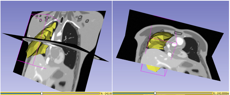
When I use the SimpleITK tool-kit to load the reference CT (i.e. RAS oriented MCR.nii.gz), the original orientation, i.e. in RAS, changes to LPS orientation. For example, when I print the physical boundaries, I get the numbers shown below.

physical point at voxel [0, 0, 0]: (444.0, 380.0, -320.0)
physical point at voxel [202, 126, 160]: (40.0, 128.0, 0.0)
Image Origin: (444.0, 380.0, -320.0)
Voxel Spacing: (2.0, 2.0, 2.0)
Image Direction: (-1.0, 0.0, 0.0, 0.0, -1.0, 0.0, 0.0, 0.0, 1.0)
Image Size: (203, 127, 161)

As a result, I modified the origin and direction of the reference CT to RAS because ITK loads an LPS-oriented image by default, as shown in the steps below. Once the previously mentioned information has been modified, save it using the code below.

reference_image = sitk.ReadImage('./MCR.nii.gz')
ref_image_out = sitk.GetImageFromArray(sitk.GetArrayFromImage(reference_image))
ref_image_out.SetOrigin((-reference_image.GetOrigin()[0], -reference_image.GetOrigin()[1], reference_image.GetOrigin()[2]))
ref_image_out.SetSpacing(reference_image.GetSpacing())
ref_image_out.SetDirection((1.0, 0.0, 0.0, 0.0, 1.0, 0.0, 0.0, 0.0, 1.0))
sitk.WriteImage(ref_image_out, './ITK_RAS/MCR.nii.gz')
physical point at voxel [0, 0, 0]: (-444.0, -380.0, -320.0)
physical point at voxel [202, 126, 160]: (-40.0, -128.0, 0.0)
Image Origin: (-444.0, -380.0, -320.0)
Voxel Spacing: (2.0, 2.0, 2.0)
Image Direction: (1.0, 0.0, 0.0, 0.0, 1.0, 0.0, 0.0, 0.0, 1.0)
Image Size: (203, 127, 161)

All of the mesh points are now within the domain of the displacement field transformation as a result of this change. I can guarantee you of this since the mesh points are now properly aligned with the reference CT volume. Furthermore, I applied the same changes to the deoformed CT volumes and DVF image volumes.

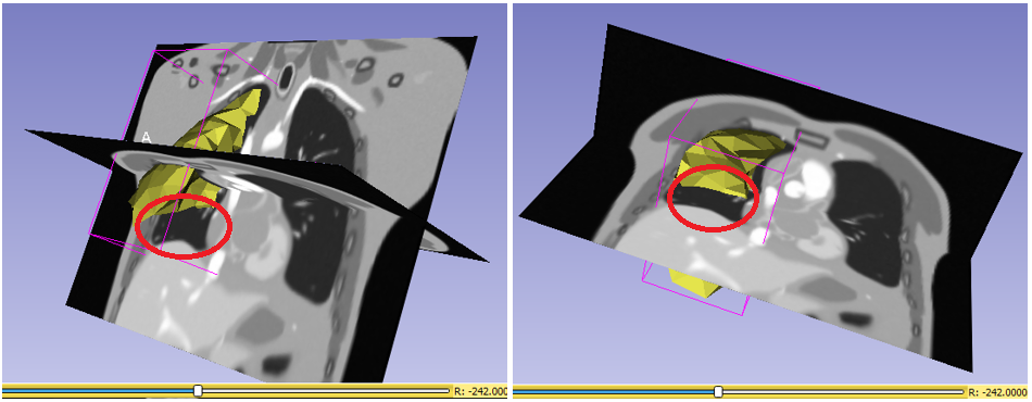
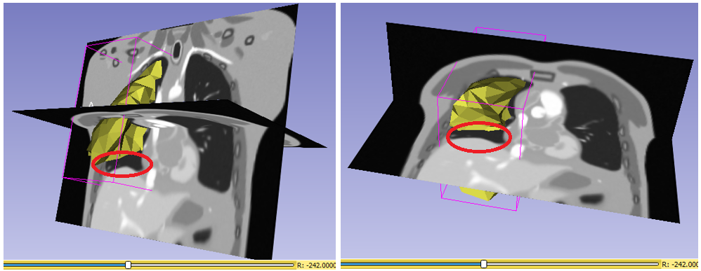
However, as I stated in the previous thread, the output mesh points after applying the displacement fields are incorrectly distorted, presumably because they are not aligned with slices in the associated deformed image volume, as I indicated above. Should I apply inverse of that transform ? or am I mssing something ?

If possible, could please help me to resolve this issue.

I frequently find I need to apply the inverse of the transform, instead of the direct transform. It is an easy thing to try, so I suggest doing that before continuing to bash your head against the wall trying to figure out what you are doing wrong.

Your deformation field is in a strange format, I would rather adjust that than modify the reference image. Changing the reference image sounds very suspicious to me.