Hello everyone.
I have 3D chest CTs whose lung contour is labeled and I generate the contour meshes.
I am trying to complete the following things:
Generate the DRR from the 3D chest CTs
Project the mesh vertex(points) onto the DRR, that means find the relation between the 3D mesh and the 2D X-ray
I have found the GetDRRSiddonJacobsRayTracing.cxx but it is a C++ code.
Is there any Python version?
If not, can the GetDRRSiddonJacobsRayTracing.cxx do the upper two things?
I also see some DRRs generated from others using the GetDRRSiddonJacobsRayTracing.cxx but the results doesn’t look like the chest X-ray, how can I fix it?
Sorry for my stupid questions.
Hello Simon, thanks for your kind reply.
Sorry for my late reaction, but I was struggling in learning the RTK
I have built a DRR python code based on the rtkforwardprojections.cxx, but the c++ code uses command line args to get the settings of the empty projection images and the geometry. I tried some settings by myself, but I cannot get correct a DRR image.
I have read the RTK geometry info pages, but I learn little from it.
Here is my target: ‘Get a front-view projection (DRR, sythetic X-ray) of a 3D chest CT and project the mesh vertex onto the DRR’
Could you please help me to find out how can I set my empty projection images and the geometry?
According to my understanding, I only need a front-view DRR, so the numberOfProjections should be 1, but other args I don’t know how to set them.
If you are interested, here is my python code, it is basically a combination of FirstReconstruction.py and my python translation from rtkforwardprojections.cxx
I don’t fully understand why you learned little from the geometry documentation. Your code seems correct but I’m guessing there are some geometry issues. Here is where I would look at:
in AddProjection, you don’t pass any parameter but source distances and angle (0). This will produce a front-view DRR only if chest.nii is such that the first coordinate is left right and the second cranio caudal (i.e., not DICOM). See geometry documentation…
you set origin to 0. If chest.nii is centered around zero, then you will only have a quarter of the DRR, you probably want to center it with origin = [-511,-511,0] (the third coordinate is not used in the projection stack)
If chest.nii is not centered around zero, you have to play with the geometry parameters but it’s simpler to change its origin to make it centered.
I hope it helps,
Simon
Sorry for my bad expression, I want to mean ‘understand little from the geometry doc’, because of my lack of medical knowledges. Your docs are really good.
After re-read the geometry doc more carefully and learn from your replies, I finally get a DRR looks correct.
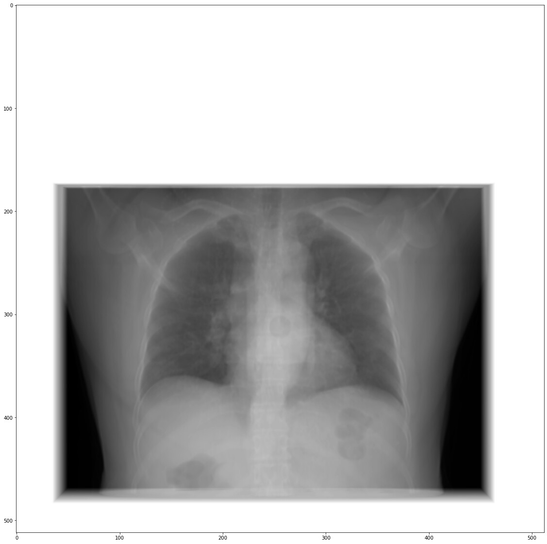
In order to set it look like X-ray, I have set the sid and sdd very large(6000, 12000). Is this correct? When I set these two params smaller(600, 1200), I got the thing more like a 3d one.
How can I set DRR without the ‘white’ part, for example, my chest CT is [301, 512, 512], so I think I should generate a [512, 301] image size? But which part controls the ‘white’ part, that means my DRR can be filled full with meaningful pixels.
If I get the matrix from the geometry, can the matrix directly be used in OpenGL to project the mesh vertex on the generated DRR image? Or other method should be used?
Sorry for my bad expression and stupid questions again. Thank you very much for helping rookies like me.
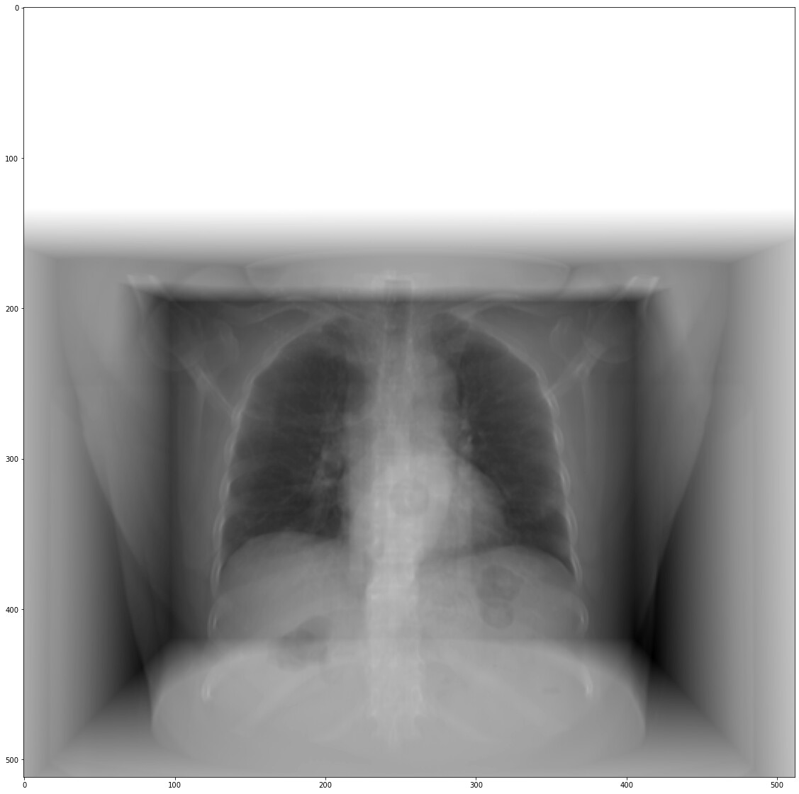
Good to hear that you’re progressing. The JosephForwardProjectionImageFilter simply calculates line integrals of your CT. The white part is probably due to rays not intersecting the CT and I’m guessing that the value is 0 there. So if values are black, they are probably below 0 which is not realistic for a DRR. you probably want to make sure that before projecting, air is at 0 by adding 1000 to the volume. Doing so, you should see less border effects with a divergent beam. There won’t be a “white part” but a “black part” and this black part will be due to the limited size of the CT image. You just have to adjust the DRR size to the CT image.
For the projection of the mesh, I am not familiar with OpenGL so I won’t be able to help. But you can use the projection matrix to project your mesh points in DRR coordinates that you may need to convert to pixel coordinates (using the origin and the spacing).