I have a CT image as DICOM file and a deformation vector field as an .mhd file, which I want to use to deform the CT. The deformation vector field is a result from a deformable registration of the CT & CBCT of the patient exportet from a treatment planning system.
So far I read in the DICOM image and also the mhd file. However, I do not know how to deform the CT image now. Can someone help me please?
Here my steps so far (python):
import simpleITK as sitk

#%% input
mhd_file = "C:/..."
dicom_dir = "C:/..."

#%% read DVF array
dvf = sitk.ReadImage(mhd_file)
dvf_array = sitk.GetArrayFromImage(dvf)

#%% read CT image (part of read_dicom_tags(dicom_dir) function I am using - found on the internet)
series_IDs = sitk.ImageSeriesReader.GetGDCMSeriesIDs(dicom_dir)
series_file_names = sitk.ImageSeriesReader.GetGDCMSeriesFileNames(
    dicom_dir, series_IDs[0])
series_reader = sitk.ImageSeriesReader()
series_reader.SetFileNames(series_file_names)
series_reader.MetaDataDictionaryArrayUpdateOn()
series_reader.LoadPrivateTagsOn()
ct_image= series_reader.Execute()
ct_array = sitk.GetArrayFromImage(ct_image)
Thank you for helping me!
PS: I am new to the processing of medical images and not the very experienced programmer (not a beginner but still…)
If you are in a rush, just go through the relevant notebooks. These are Image Details, Transforms and Transforms and Resampling. After you go over these notebooks you should be able to easily solve your problem.
Please feel free to ask additional questions if things aren’t clear from those notebooks.
@zivy Thanks for referring to the notebook repository and tutorial.
What I have tried is:
#%% deforming CT to CBCT with dvf
displacement = sitk.DisplacementFieldTransform(dvf)
displacement.SetInterpolator(sitk.sitkNearestNeighbor)
resampler = sitk.ResampleImageFilter()
resampler.SetTransform(displacement)
resampler.SetReferenceImage(ct_image)
deformed  = resampler.Execute(ct_image)
However, when I am visually comparing this result with the original registration output (it was exported from the TPS too) it is not the same. I was expecting a difference because of the interpolation, which is most likely not the same, but it the results are not even close.
I was wondering if I am applying “the right direction” (I did not perform and export the registration) so I tried:
Thank you for the advice to use 3D Slicer. Indeed I get similar results there.
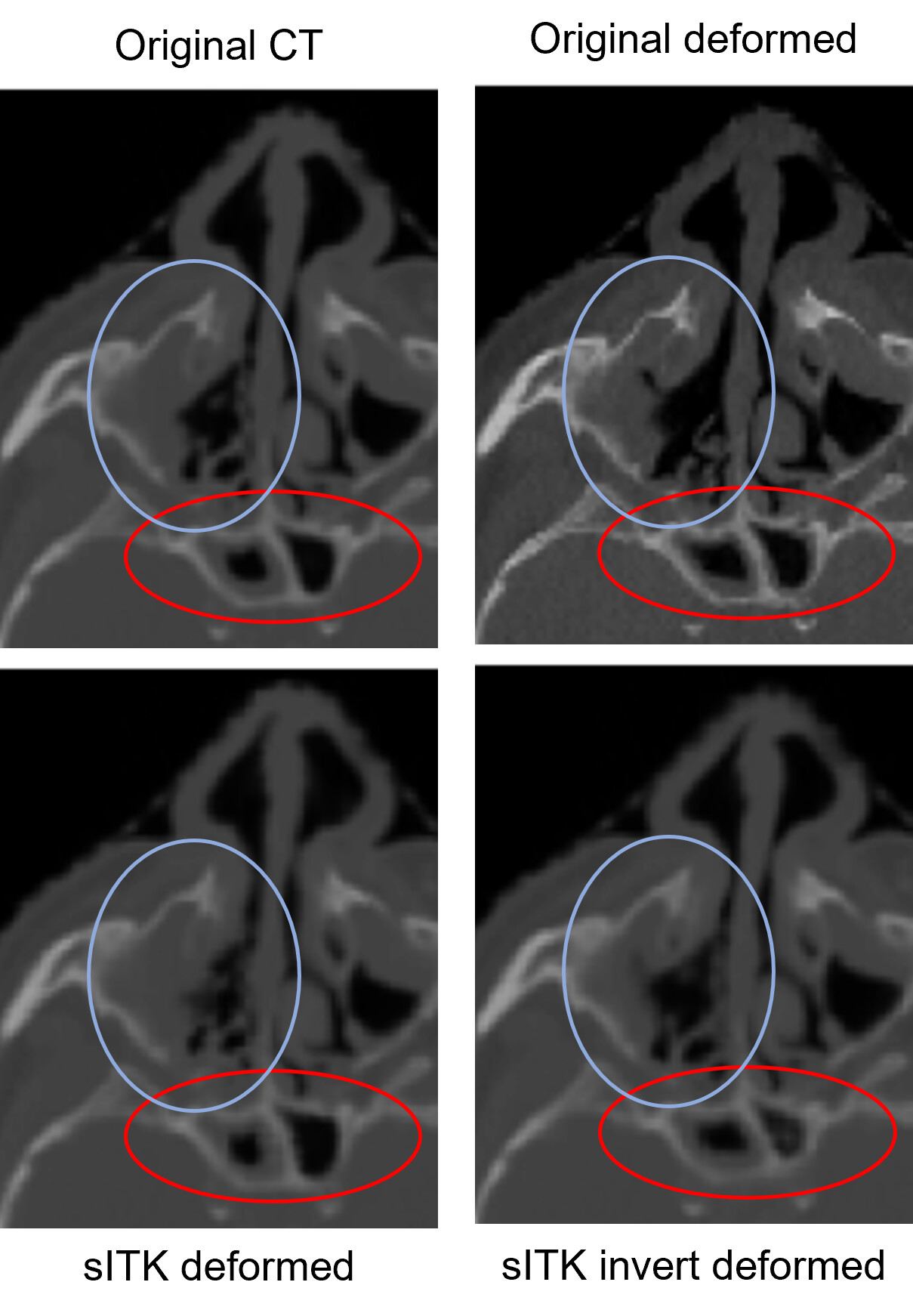
The “original deformed” is the result of the deformation exported from the treatment planning system
The “sITK deformed” is the deformed CT using the DVF (exported from the treatment planning system, where the DIR was performed) in sitk/3D slicer
The “sITK invert deformed” - dont care about that one, i checked the inverted
What I am confused about is that I expected “sITK deformed” to be similar to “original deformed” as both are the results from the same CT and DVF. But this is not the case (visible in blue circle).