I want to solve a 3D (CT) - 2D (fluoro/xray) registration task. I have found out so far that the most straightforward option is to first generate DRR based on CT and then register them.
I am not sure how a generation of DRR works - I know there exist solutions in RTK, [ITK], or 3DSlicer (DRR module / Volume Rendering module); however, I lack the background information I need for that. I haven’t found a good resource to learn from. Is there any good book/webinar that explains this?
I have SID/voxel spacing information from the attached CT di-comm headers. How can I use them as an approximation for DRR generation?
Could somebody share the optimal way in SITK how to register it?
Unfortunately, SimpleITK does not support 2D/3D (perspective-projection-image/volume) registration.
I highly recommend that you formulate the task more rigorously, 2D/3D registration covers a very broad set of problems. As a starting point, is the imaged object rigid or deformable (liver vs. bone), is it a single object or multiple objects (multiple bones that can move independently or a single bone) etc.
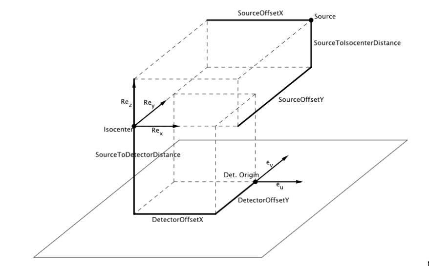
I don’t have a good reading for DRR. You can indeed use RTK and I include a simple example below to project an input ct.mha to a 3D stack of projections drr.mha using RTK Python package. The difficulty might be to understand RTK’s geometry which is explained here.
#!/usr/bin/env python
import sys
import itk
from itk import RTK as rtk

# Defines the image type
ImageType = itk.Image[itk.F,3]

# Defines the RTK geometry object
geometry = rtk.ThreeDCircularProjectionGeometry.New()
numberOfProjections = 360
firstAngle = 0.
angularArc = 360.
sid = 600 # source to isocenter distance
sdd = 1200 # source to detector distance
for x in range(0,numberOfProjections):
  angle = firstAngle + x * angularArc / numberOfProjections
  geometry.AddProjection(sid,sdd,angle)

# Writing the geometry to disk
xmlWriter = rtk.ThreeDCircularProjectionGeometryXMLFileWriter.New()
xmlWriter.SetFilename ( 'geometry.xml' )
xmlWriter.SetObject ( geometry )
xmlWriter.WriteFile()

# Create a stack of empty projection images
ConstantImageSourceType = rtk.ConstantImageSource[ImageType]
constantImageSource = ConstantImageSourceType.New()
origin = [ -127, -127, 0. ]
sizeOutput = [ 128, 128,  numberOfProjections ]
spacing = [ 2.0, 2.0, 2.0 ]
constantImageSource.SetOrigin( origin )
constantImageSource.SetSpacing( spacing )
constantImageSource.SetSize( sizeOutput )
constantImageSource.SetConstant(0.)

# Read projected image
inputCT = itk.imread('ct.mha')

# Pr
JosephType = rtk.JosephForwardProjectionImageFilter[ImageType, ImageType]
joseph = JosephType.New()
joseph.SetGeometry( geometry )
joseph.SetInput(constantImageSource.GetOutput())
joseph.SetInput(1, inputCT)

itk.imwrite(joseph.GetOutput(), 'drr.mha')
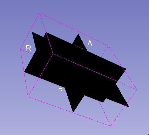
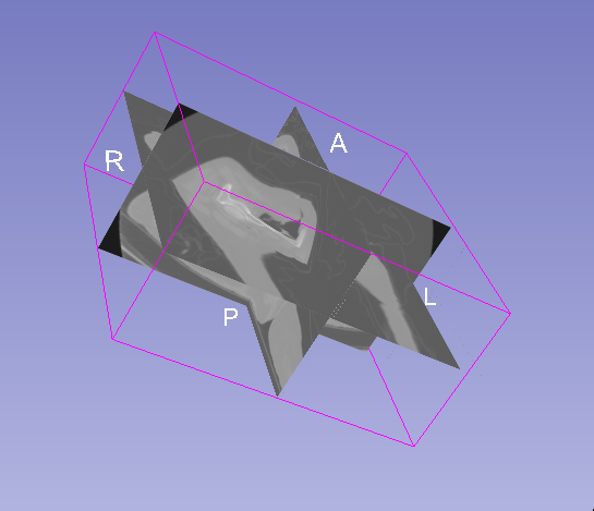
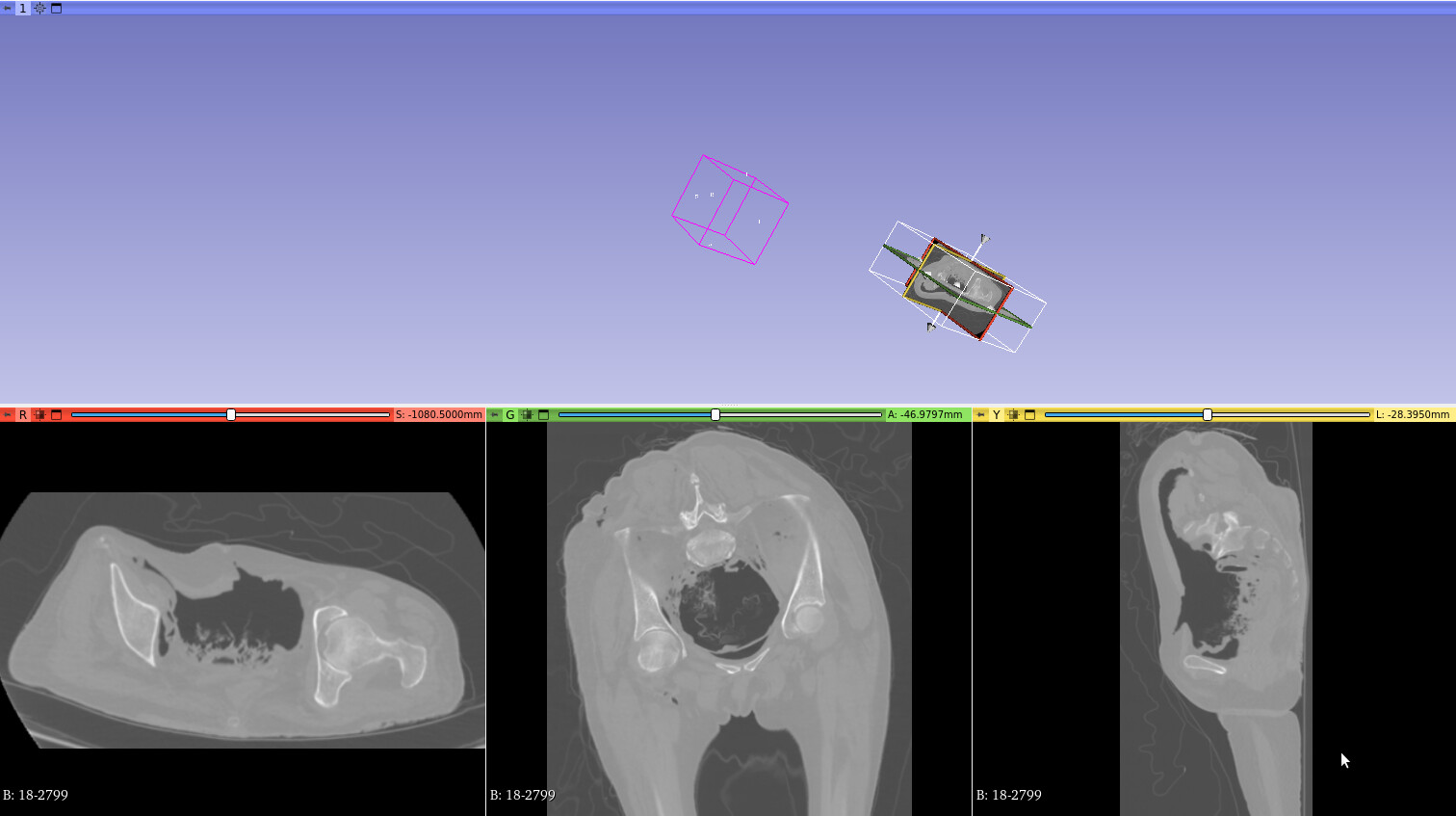
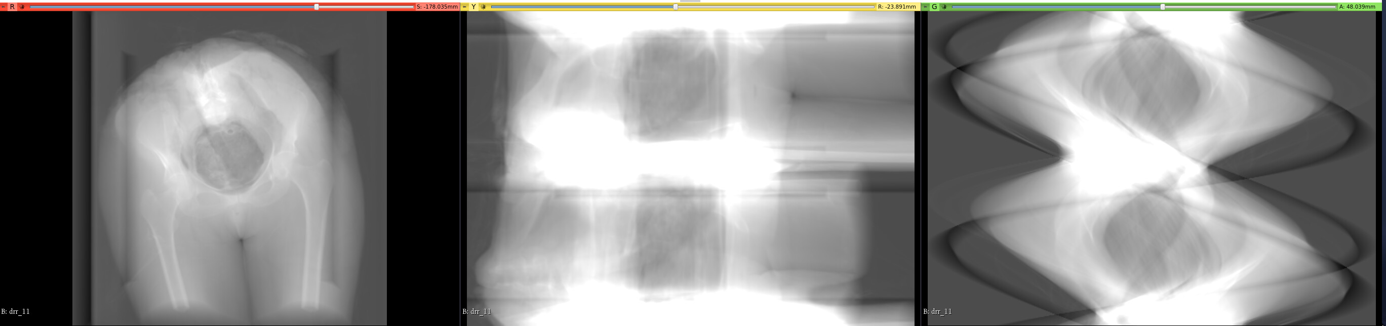
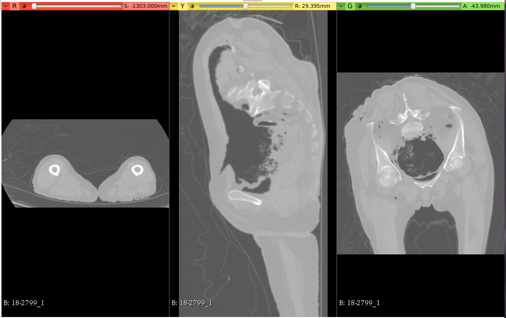
The first slice (red) corresponds to the feet-to-head view; therefore, it should represent the RTK y-axis. The y-axis according to the ZXY convention should be last → therefore, you changed the direction for the first array to [0, 0, 1].
The second slice (yellow) on my volume corresponds to left-to-right, which is the x-axis in RTK. According to the ZXY convention, it’s in second place; we put [0, 1, 0] in the direction vector.
The third image is an AP-PA view, which according to ZXY should be first. We put [-1, 0, 0] in the direction.
The geometry is key and is not straightforward to understand so no worries. Forget about the Euler convention, this is not important here because you rotate around one axis only so the order does not matter. What matters is that the GantryAngle is for the Y axis. In other words, the axis around which you rotate is Y in your image.
The DICOM convention (which your image follows I believe) sets the cranio caudal / feed to head direction in the Z direction. So if this is the direction around which you rotate, you must transform Z to Y before passing your image. This can be done using the direction matrix and the second line of the direction matrix transforms voxels in the Z direction to coordinates in the Y directions. The other directions have been swapped (first line transforms Y to X and third line transforms X to Z + mirrors it).
I am not commenting your assumptions because you express everything in terms of anatomical orientation and RTK makes no assumption on this. All it does is place the source at location (SID,0,0) for GantryAngle 0°, (0,0,SID) for GantryAngle 90° etc.