Dear Dženan Zukić and Dear Ziv Yaniv
I sincerely thank you for your support and guidance.
I apologize for the delay in sending the images and codes. I send the shared links the following files using Dropbox:
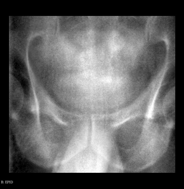
EPID.nrrd
DRR.nrrd
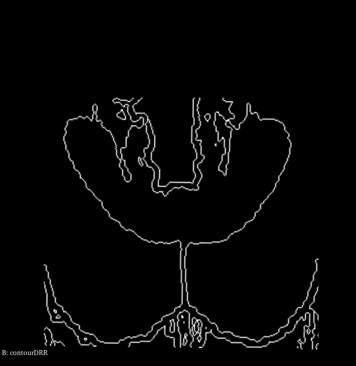
contourDRR.nrrd
At firstly, I should point out that the contourDRR.nrrd file contains the edge of pelvic in the DRR.nrrd file. That’s why I send the shared link DRR.nrrd file.
I have to emphasize that I’m looking for a way (any filter in SimpleITK) to extract the pelvic edge in the EPID image by deforming the edge in the contourDRR image, for example using Active Contour Filters in SimpleITK.
Ziv Yaniv had told me to do the following steps:
1- Resample the contour image using nearest neighbor interpolator onto the EPID image (identity transformation).
2- Convert binary representation obtained from step 1 into a distance map.
3- Compute edge potential map from EPID image.
4- Use outputs from step 2 and 3 as inputs for the GeodesicActiveContourLevelSetImageFilter .
I tried to do these steps as Ziv Yaniv pointed out as following:
Step 1: Resample the contour image using nearest neighbor interpolator onto the EPID image (identity transformation)
#Modules
import SimpleITK as sitk
from SimpleITK import ResampleImageFilter

#Read EPID and contourDRR images in nrrd format
EPID = sitk.ReadImage('EPID.nrrd')
contourDRR = sitk.ReadImage('contourDRR.nrrd')

#Get origin coordinates
originEPID = EPID.GetOrigin()

#Get size (Matrix Size.
matrixSizeEPID = EPID.GetSize()

#Get image spacing ((0.25, 0.25, 1.0)
spacingSizeEPID = EPID.GetSpacing()

#Create and initialize the filter of ResampleImageFilter
myFilterResampleImage = ResampleImageFilter()

#Set Interpolator to NearestNeighbor
myFilterResampleImage.SetInterpolator(sitk.sitkNearestNeighbor)

#Set Origin coordinates according with the origin of EPID.
myFilterResampleImage.SetOutputOrigin((-1*originEPID[0], -1*originEPID[1], originEPID[2]))

#Set spacing according with the spacing of EPID.
myFilterResampleImage.SetOutputSpacing(spacingSizeEPID)

#Set matrix size according with the matrix size of EPID.
myFilterResampleImage.SetSize(matrixSizeEPID)

#Set the pixel value
myFilterResampleImage.SetDefaultPixelValue(0.0)

#Set Pixel Type
myFilterResampleImage.SetOutputPixelType(sitk.sitkInt8)

#Set Transform (Identity Transorm)
transform = sitk.Transform()
transform.SetIdentity()
myFilterResampleImage.SetTransform(transform)

#Execute the filter (ResampleImageFilter) on the input image (contourDRR)
contourDRRMatched = myFilterResampleImage.Execute(contourDRR)

#Save Image (contourDRRMatched) in nrrd format
writerResampleImageFilter = sitk.ImageFileWriter()
writerResampleImageFilter.SetFileName('contourDRRMatched.nrrd')
writerResampleImageFilter.Execute(contourDRRMatched)
Step 2: Convert binary representation obtained from step 1 into a distance map.
#Module
import SimpleITK as sitk
from SimpleITK import SignedMaurerDistanceMapImageFilter

#Read contourDRRMatched image in nrrd format
contourDRRMatched = sitk.ReadImage('contourDRRMatched.nrrd')

#Create the filter of SignedMaurerDistanceMapImageFilter
myFilterSignedMaurerDistanceMap = SignedMaurerDistanceMapImageFilter()

#Set Background Value
myFilterSignedMaurerDistanceMap.SetBackgroundValue(0.0)

#Set if the inside represents positive values in the signed distance map.
myFilterSignedMaurerDistanceMap.SetInsideIsPositive(False)

#Set if the distance should be squared
myFilterSignedMaurerDistanceMap.SetSquaredDistance(True)

#Set if image spacing should be used in computing distances
myFilterSignedMaurerDistanceMap.SetUseImageSpacing(False)

#Execute the filter (SignedMaurerDistanceMapImageFilter) on the input image (contourDRR)
contourDRRMatchedDistanceMap = myFilterSignedMaurerDistanceMap.Execute(contourDRRMatched)

#Save Image (contourDRRMatchedDistanceMap) in nrrd format
writerSignedMaurerDistanceMapImageFilter = sitk.ImageFileWriter()
writerSignedMaurerDistanceMapImageFilter.SetFileName('contourDRRMatchedSignedMaurerDistanceMap.nrrd')
writerSignedMaurerDistanceMapImageFilter.Execute(contourDRRMatchedDistanceMap)
Step 3: Compute edge potential map from EPID image.
It should be noted that the potential edge map of the EPID image cannot be calculated directly through the EdgePotentialImageFilter filter. I get the following error message:
#Module
import SimpleITK as sitk
from SimpleITK import EdgePotentialImageFilter

#Read Graient EPID image in nrrd format
EPID = sitk.ReadImage('EPID.nrrd')

#Create the filter of EdgePotentialImageFilter
myFilterEdgePotential = EdgePotentialImageFilter()

#Execute the filter (EdgePotentialImageFilter) on the input image (EPID)
EPIDGradientEdgePotential = myFilterEdgePotential.Execute(EPID)
...
RuntimeError: Exception thrown in SimpleITK EdgePotentialImageFilter_Execute: /tmp/SimpleITK/Code/Common/include/sitkMemberFunctionFactory.hxx:158:

sitk::ERROR: Pixel type: 64-bit float is not supported in 3D by N3itk6simple24EdgePotentialImageFilterE.
For solving it, I calculated the gradient of EPID image with the following code:
#Module
import SimpleITK as sitk
from SimpleITK import GradientImageFilter

#Read EPID image in nrrd format
EPID = sitk.ReadImage('EPID.nrrd')

#Create the filter of GradientImageFilter
myFilterGradient = GradientImageFilter()

#UseImageDirection flag
myFilterGradient.SetUseImageDirection(False)

#SetUseImageSpacing flag
myFilterGradient.SetUseImageSpacing(True)

#Execute the filter (GradientImageFilter) on the input image (EPID)
EPIDGradient = myFilterGradient.Execute(EPID)

#Save Image (EPIDGradient) in nrrd format
writerGradientImageFilter = sitk.ImageFileWriter()
writerGradientImageFilter.SetFileName('EPIDGradient.nrrd')
writerGradientImageFilter.Execute(EPIDGradient)
At now, I can use EdgePotentialImageFilter as following:
#Module
import SimpleITK as sitk
from SimpleITK import EdgePotentialImageFilter

#Read Graient EPID image in nrrd format
EPIDGradient = sitk.ReadImage('EPIDGradient.nrrd')

#Create the filter of EdgePotentialImageFilter
myFilterEdgePotential = EdgePotentialImageFilter()

#Execute the filter (EdgePotentialImageFilter) on the input image (EPIDGradient)
EPIDGradientEdgePotential = myFilterEdgePotential.Execute(EPIDGradient)

#Save Image (EPIDGradientEdgePotential) in nrrd format
writerEdgePotentialImageFilter = sitk.ImageFileWriter()
writerEdgePotentialImageFilter.SetFileName('EPIDGradientEdgePotential.nrrd')
writerEdgePotentialImageFilter.Execute(EPIDGradientEdgePotential)
Step 4: Use outputs from step 2 and 3 as inputs for the GeodesicActiveContourLevelSetImageFilter .
At the final step, I want to use the filter to deform the edges in the image ` DRRMatched.
I have to emphasize that I expected one of the two inputs of this
filter to be the image DRRMatched, if this is not the case.
Anyway, I execute the following code.
#Modules
import SimpleITK as sitk
from SimpleITK import GeodesicActiveContourLevelSetImageFilter
#Read EPID and contourDRR images in nrrd format
input1 = sitk.ReadImage('contourDRRMatchedSignedMaurerDistanceMap.nrrd')
input2 = sitk.ReadImage('EPIDGradientEdgePotential.nrrd')
#Create the filter of GeodesicActiveContourLevelSetImageFilter
myFilterGeodesicActiveContourLevelSet = GeodesicActiveContourLevelSetImageFilter()
myFilterGeodesicActiveContourLevelSet.SetAdvectionScaling(1.0)
myFilterGeodesicActiveContourLevelSet.SetCurvatureScaling(1.0)
myFilterGeodesicActiveContourLevelSet.SetDebug(False)
myFilterGeodesicActiveContourLevelSet.SetMaximumRMSError(0.01)
myFilterGeodesicActiveContourLevelSet.SetNumberOfIterations(1000)
myFilterGeodesicActiveContourLevelSet.SetNumberOfThreads(8)
myFilterGeodesicActiveContourLevelSet.SetNumberOfWorkUnits(0)
myFilterGeodesicActiveContourLevelSet.SetPropagationScaling(1.0)
myFilterGeodesicActiveContourLevelSet.SetReverseExpansionDirection(False)
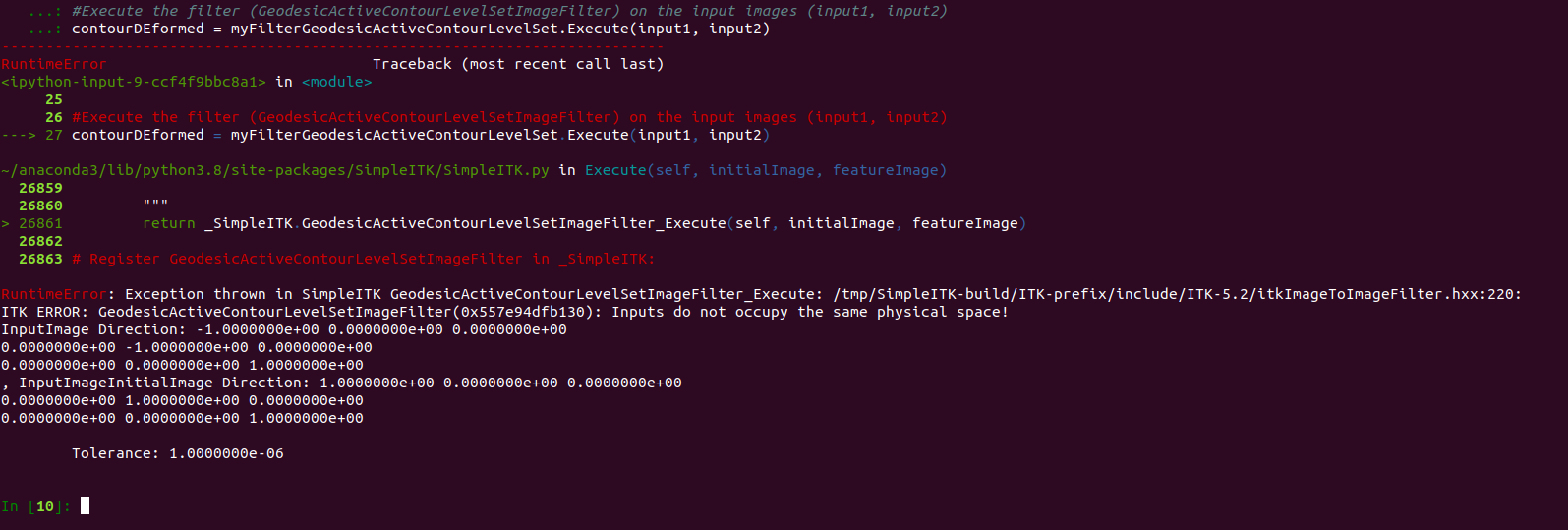
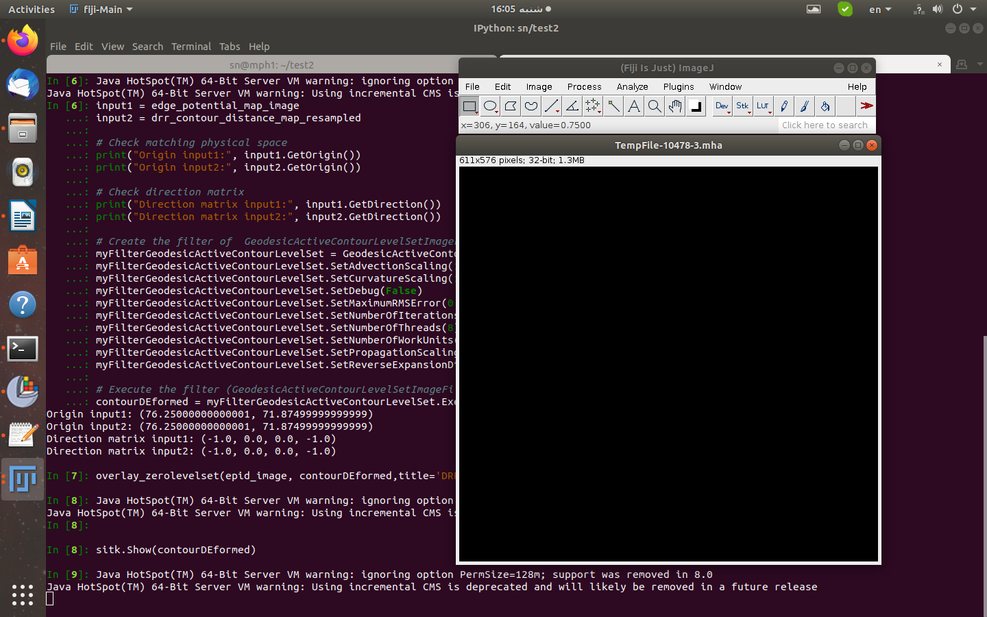
#Execute the filter (GeodesicActiveContourLevelSetImageFilter) on the input images (input1, input2)
contourDEformed = myFilterGeodesicActiveContourLevelSet.Execute(input1, input2)
I get the following error message:
Error Message:
RuntimeError:
Exception thrown in SimpleITK
GeodesicActiveContourLevelSetImageFilter_Execute:
/tmp/SimpleITK/Code/Common/include/sitkProcessObject.h:354:

sitk::ERROR:
Failure to convert SimpleITK image of dimension: 3 and pixel type:
"64-bit float" to ITK image of dimension: 3 and pixel type:
"32-bit float"!
I think my pipeline is wrong. As I mentioned above, I want to get the
bone contour in the EPID image by Active Contour method by deforming
the contourDRRMatched contour.
Please guide me.
Best regards.
Shahrokh