BSplineTransform with displacement approaching zero at image boundary

According to the documentation and some experiments, the BSplineTransform deformation is zero outside the support region of the coefficient images (but non-zero at the boundary, i.e. there is a discontinuity).

I would like to enforce that the deformation smoothly approaches zero from the inside of the support region. Is there any recommended/tested/implemented way of doing this?

I guess following algorithm might work:

  • convert the BSplineTransform to a dense displacement field (e.g. TransformToDisplacementFieldFilter)
  • modify displacement field so it smoothly approaches zero at boundary
  • fit BSplineTransform from manipulated displacement field, e.g. with DisplacementFieldToBSplineImageFilter

Any other ideas? What is the interpretation of the BSplineTransform coefficient images? Could I directly manipulate the coefficients?

The use case is the following. I want to locally adapt a skull model to better fit a reference model around the eyes/nose. At the boundary of the BSplineTransform support region (where green surface ends) I I don’t want the step in the deformation field/i.e. a smooth transition to zero.

1 Like

I’m so glad you brought up this topic. As you have realized, continuity of the displacement field across the full 3D domain is very important. The main reason is that you cannot compute inverse of the transform near discontinuities and you need to compute inverse transform if you want to transform points, meshes, etc. along with images.

In 3D Slicer we generally use ITK for computing transforms but then put them into VTK transforms for any visualization or processing, because in VTK transforms the field is gradually converges to zero and VTK can compute the inverse transform (and gradient) anywhere, on-demand, for a single point just as well for an entire volume, for any transform type, even for composite transforms (consisting of a sequence of arbitrary transforms, with any of them inverted).

ITK transforms have the advantage of various parametrizations, so that they can be plugged directly into optimizers.

Ideally, ITK and VTK transform infrastructure should be merged. It could be in an external library so that both VTK and ITK can use it. The parametrizations could be included in this new library or it could remain in ITK. However, this would be major effort for both ITK and VTK, so it would require dedicated funding.

Until this happens, you can rely on 3D Slicer for converting between ITK and VTK transforms: load your ITK transform into Slicer and use the Transforms module for managing and applying transforms. All the features are exposed in Python, so you don’t need to use the GUI if you want to do batch processing.

2 Likes

Hi Andras

Thanks for your answer and pointing me in this direction. It seems the code in slicer just copies the coefficient images (with some LPS-RAS conversion, but no special changes for the border mode) and sets the boder mode to zero:

It seems the border mode is mainly handled on the fly by vtkBSplineTransform

I will try the module in slicer to see how it behaves. Would you by chance have an snippet that shows how the resampling can be done (loading from file(s), resampling, saving result to file)?

Thanks!

Exactly. You don’t need to do anything special with the transform data, just copy that to the VTK object and let VTK to do the computations.

When border mode is set to zero it means that the transform converges to zero as you get far away, but it does not happen abruptly, so the inverse can be computed.

I would recommend to get started by using the GUI because you can then do each operation by 1-2 clicks. You can load all files (images, transforms, meshes, point lists, curves, etc) by drag-and-drop files to the application window and then use Transforms module to apply it to the loaded data. You can find coding examples here.

1 Like

Hi @lassoan

I see this topic has been an issue for while and you have already invested time into making VTK better support oriented images. The list of classes that need to be adapted seems daunting though.

Is it only the BSplineTransform where the VTK transform has continuous behavior (compared to discontinuous behavior of ITK), or are there other transforms that are also affected?

If it is only the BSpline transform, maybe the easiest would be to add a BSplineTransform based on the VTK implementation to ITK (with the corresponding api).

Most ITK transform classes only differ in parametrization. For example there are many classes for linear transforms, which (once they are computed) can be all applied the same way. So, maybe there is not that many classes to be reworked if the parametrization is separated from the use of the computed transform.

There are 4 main classes: linear, displacement field, bspline, kernel. As far as I remember, grid and bspline are discontinuous at the boundary. The main issue is that ITK developers did not have the requirements of continuity and on-the-fly inverse computation in mind when designing the transforms infrastructure, so it is hard to tell what exactly are missed and where. Even small things like not having an “inverse” flag in the transform file may require a lot of work to properly fix.

In the short term, probably yes. In the long term, maintenance, support, and bugfixes tends to require more overall effort than the initial implementation. Duplicating code would double this effort, while creating a separate library that could be used from both ITK and VTK would not.

2 Likes

I have tried importing the transform in slicer and transforming the moving image and it helps. Is there a way to specify the fixed image in the resampling (harden transform) process (I looked in the GUI and python api). I assume this means slicer is resampling on to the moving image grid. So if I need the image/labels on the fixed image grid I would need to resample again?

Meanwhile I have implemented a poor mans alternative using SimpleITK.

  • convert bspline to displacement transform
  • pad displacement field with a linear ramp (zero at border)
def bspline_to_displacement_field_transform(
    initial_bspline_tx: sitk.BSplineTransform,
    grid_spacing: float = 1.0,
    variance_update_field: float = 1.75,
    variance_total_field: float = 0.5,
) -> sitk.DisplacementFieldTransform:
    physical_size = initial_bspline_tx.GetTransformDomainPhysicalDimensions()
    # The deformation field spacing affects the accuracy of the transform approximation,
    output_spacing = [grid_spacing] * initial_bspline_tx.GetDimension()
    output_size = [
        int(phys_sz / spc + 1) for phys_sz, spc in zip(physical_size, output_spacing)
    ]
    displacement_field_transform = sitk.DisplacementFieldTransform(
        sitk.TransformToDisplacementField(
            initial_bspline_tx,
            outputPixelType=sitk.sitkVectorFloat64,
            size=output_size,
            outputOrigin=initial_bspline_tx.GetTransformDomainOrigin(),
            outputSpacing=output_spacing,
            outputDirection=initial_bspline_tx.GetTransformDomainDirection(),
        )
    )
    displacement_field_transform.SetSmoothingGaussianOnUpdate(
        variance_update_field, variance_total_field
    )
    return displacement_field_transform


def zero_padding(transform: sitk.DisplacementFieldTransform, pad: int = 4):
    """Pad displacement field with a linear ramp reaching zero at border"""
    field = transform.GetDisplacementField()
    field_np = sitk.GetArrayFromImage(field)

    field_np_pad = np.pad(field_np, pad_width=((pad, pad), (pad, pad), (pad, pad), (0, 0)), mode="constant")
    for k in range(3):
        component_np_pad = np.pad(field_np[..., k], pad_width=pad, mode="linear_ramp")
        field_np_pad[..., k] = component_np_pad

    displacement_field2 = sitk.GetImageFromArray(field_np_pad, isVector=True)
    # helper to for padded origin etc, needed for CopyInformation below 
    dummy_np = np.ones_like(field_np[..., 0], dtype=np.uint8)
    dummy = sitk.GetImageFromArray(dummy_np)
    dummy.CopyInformation(field)
    displacement_field2.CopyInformation(sitk.ConstantPad(dummy, [pad] * 3, [pad] * 3))

    transform2 = sitk.DisplacementFieldTransform(3)
    transform2.SetDisplacementField(displacement_field2)
    return transform2

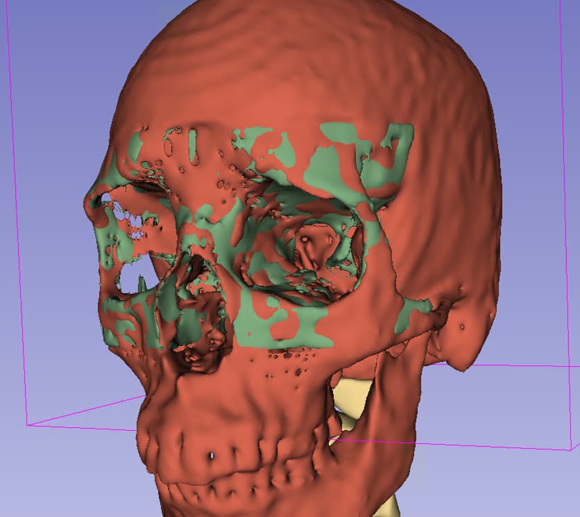
Green is using the unmodified bspline transform:
image

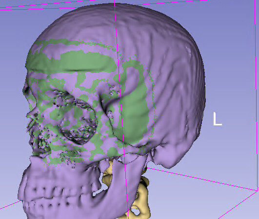
Purple is using the padded displacement transform:
image

I would like to enforce that the deformation smoothly approaches zero from the inside of the support region. Is there any recommended/tested/implemented way of doing this?

The displacement field transforms support enforcement of a stationary boundary. These even include invertible methods such as B-spline SyN.

Underlying all these B-spline methods is a bit of a different approach than your standard free-form deformation algorithm, as described here. At their core (including the DisplacementFieldToBSplineImageFilter), they all employ the B-spline scattered data filter.

3 Likes