Hello,
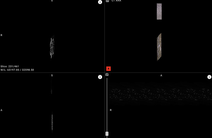
I am new to ITK and try to apply a 3D rotation to CT image data. I have an object which is positioned with an angle in the CT. Therefore, I would like to apply a rotation, so that viewing the dataset wouldn’t “shift” by scrolling through it. In order to compute the orientation of the dataset I perform a PCA analysis and hence I can compute the rotation matrix. I looked at the notebooks and other examples and experimented already with a few resampling configurations and transformations but unfortunately I never get the desired result.
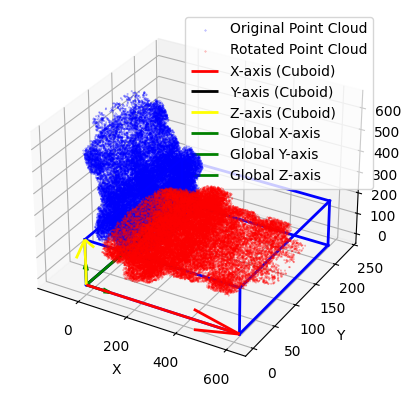
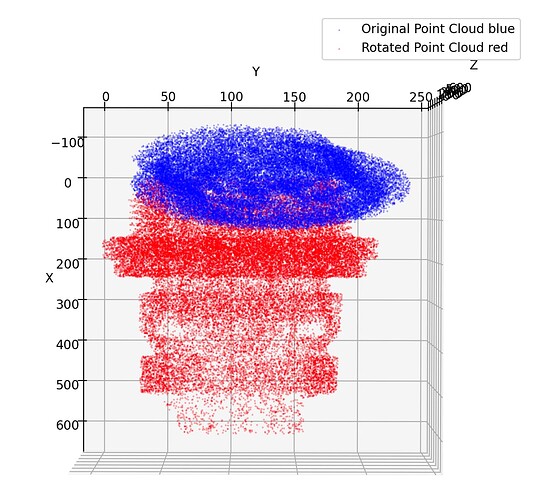
In this image I visualized the original dataset in blue and the dataset after applying the rotation matrix in red (without ITK). The object axes (cuboid) now align with the global coordinate system.

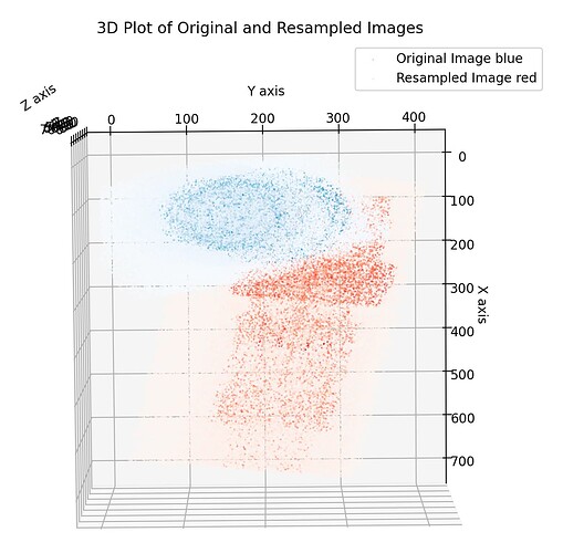
However, due to PCA I lost the information about the correct axis, meaning z-axis is now x-axis. This might be problematic for resampling? I feel like I still have the output_direction, output_size or output_spacing wrong. This is the current result:
I would appreciate any hint.
Best,
jjs ![]()
Below you find the current version of the code, where I used the 2D notebook example as a guide.
def apply_3d_rotation_with_matrix(input_folder, rotation_matrix):
    """
    Rotate a 3D image using a specified rotation matrix and resample

    Parameters:
        image (sitk.Image): The 3D image to rotate.
        rotation_matrix

    Returns:
        sitk.Image: The rotated 3D image.
    """

    reader = sitk.ImageSeriesReader()
    dicom_series = reader.GetGDCMSeriesFileNames(input_folder)
    reader.SetFileNames(dicom_series)
    image = reader.Execute()

    # Create a 3D Affine transformation and set the rotation matrix
    affine_transform = sitk.AffineTransform(3)

    # Set the rotation matrix
    affine_transform.SetMatrix(rotation_matrix)

    # Set the center of the rotation to the center of the image
    image_center = image.TransformContinuousIndexToPhysicalPoint(
        np.array(image.GetSize()) / 2.0
    )

    affine_transform.SetCenter(image_center)

    # Determine extreme points to find the bounding box of the transformed image
    extreme_points = [
        (0, 0, 0),
        (image.GetWidth(), 0, 0),
        (image.GetWidth(), image.GetHeight(), 0),
        (0, image.GetHeight(), 0),
        (0, 0, image.GetDepth()),
        (image.GetWidth(), 0, image.GetDepth()),
        (image.GetWidth(), image.GetHeight(), image.GetDepth()),
        (0, image.GetHeight(), image.GetDepth()),
    ]

    # Transform the extreme points to physical space
    extreme_points_physical = [image.TransformIndexToPhysicalPoint(pnt) for pnt in extreme_points]
    inv_affine_transform = affine_transform.GetInverse()
    transformed_points = [inv_affine_transform.TransformPoint(pnt) for pnt in extreme_points_physical]

    # Calculate new bounding box
    min_x = min(p[0] for p in transformed_points)
    min_y = min(p[1] for p in transformed_points)
    min_z = min(p[2] for p in transformed_points)
    max_x = max(p[0] for p in transformed_points)
    max_y = max(p[1] for p in transformed_points)
    max_z = max(p[2] for p in transformed_points)

    # Define output image properties
    output_spacing = image.GetSpacing()
    output_direction = image.GetDirection()
    output_origin = [min_x, min_y, min_z]
    output_size = [
        int((max_x - min_x) / output_spacing[0]),
        int((max_y - min_y) / output_spacing[1]),
        int((max_z - min_z) / output_spacing[2]),
    ]


    # Perform the resampling
    resampled_image = sitk.Resample(
        image,
        output_size,
        affine_transform,
        sitk.sitkLinear,
        output_origin,
        output_spacing,
        output_direction,
        0,  # Default pixel value for out-of-bounds
        image.GetPixelID()
    )
    return resampled_image


