# 3D Affine:Rotate on two different axes one after the other
**URL:** https://discourse.itk.org/t/3d-affine-rotate-on-two-different-axes-one-after-the-other/5315
**Category:** Algorithms
**Tags:** itk, python, 3d, rotation
**Created:** [September 4, 2022, 8:32am UTC](https://discourse.itk.org/t/3d-affine-rotate-on-two-different-axes-one-after-the-other/5315 "2022-09-04T08:32:46Z")
**Posts on this page:** 8
**Page:** 1
### Author:  [@wic94016](https://discourse.itk.org/u/wic94016)
#### Post date: [September 4, 2022, 8:32am UTC](https://discourse.itk.org/t/3d-affine-rotate-on-two-different-axes-one-after-the-other/5315/1 "2022-09-04T08:32:46Z")
Hey guys,I have a serious question about my python code.
What I want to do is ,if I have a 3D array like this
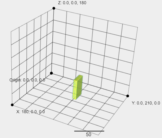
and I want it to be 90 degrees around the -X axis first,then 10 degrees around the y axis.
But it seems to wrap 90 degrees around the -X axis first, then 10 degrees around the z axis.
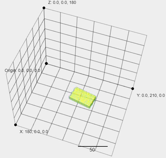
I don’t know why this is happening, it’s been bothering me for a long time, hope someone can tell me how.
The code below is what I wrote.
```auto
degrees1 = 90
rads1 = -(degrees1 )* math.pi / 180
degrees2 = 10
rads2 = -(degrees2 )* math.pi / 180
degrees = 0
rads = degrees * math.pi / 180
```
```auto
u=-1
v=0
w=0
S_mni1=np.array([[u**2+(v**2+w**2)*math.cos(rads1) , u*v*(1-math.cos(rads1))-w*math.sin(rads1) , u*w*(1-math.cos(rads1))+v*math.sin(rads1) , 0],
[u*v*(1-math.cos(rads1))+w*math.sin(rads1) , v**2+(u**2+w**2)*math.cos(rads1) , v*w*(1-math.cos(rads1))-u*math.sin(rads1) , 0],
[u*w*(1-math.cos(rads1))-v*math.sin(rads1) , v*w*(1-math.cos(rads1))+u*math.sin(rads1) , w**2+(u**2+v**2)*math.cos(rads1) , 0],
[0,0,0,1]])
u=0
v=1
w=0
S_mni2=np.array([[u**2+(v**2+w**2)*math.cos(rads2) , u*v*(1-math.cos(rads2))-w*math.sin(rads2) , u*w*(1-math.cos(rads2))+v*math.sin(rads2) , 0],
[u*v*(1-math.cos(rads2))+w*math.sin(rads2) , v**2+(u**2+w**2)*math.cos(rads2) , v*w*(1-math.cos(rads2))-u*math.sin(rads2) , 0],
[u*w*(1-math.cos(rads2))-v*math.sin(rads2) , v*w*(1-math.cos(rads2))+u*math.sin(rads2) , w**2+(u**2+v**2)*math.cos(rads2) , 0],
[0,0,0,1]])
S_mni=S_mni2.dot(S_mni1)
u=S_mni[0][2]
v=S_mni[1][2]
w=S_mni[2][2]
Trot=np.array([[u**2+(v**2+w**2)*math.cos(rads) , u*v*(1-math.cos(rads))-w*math.sin(rads) , u*w*(1-math.cos(rads))+v*math.sin(rads) , 0],
[u*v*(1-math.cos(rads))+w*math.sin(rads) , v**2+(u**2+w**2)*math.cos(rads) , v*w*(1-math.cos(rads))-u*math.sin(rads) , 0],
[u*w*(1-math.cos(rads))-v*math.sin(rads) , v*w*(1-math.cos(rads))+u*math.sin(rads) , w**2+(u**2+v**2)*math.cos(rads) , 0],
[0,0,0,1]])
Msvs=Trot.dot(S_mni)
```
```auto
vx_mni=np.zeros(size_img,dtype=float)
vx_mni[0:50,0:10,0:30]=1
x=40-1
y=120-1
z=90-1
sz_1=50
sz_2=10
sz_3=30
move=np.array([-math.floor(z-(sz_3/2))-1,-math.floor(y-(sz_2/2))-1,-math.floor(x-(sz_1/2))-1])
```
```auto
img_volume = vx_mni
itk_img_volume = itk.GetImageFromArray(img_volume)
TransformType = itk.AffineTransform[itk.D, 3]
affine_transform = TransformType.New()
params = itk.OptimizerParameters[itk.D](12)
params[0] = Msvs[0][0].item()
params[1] = Msvs[0][1].item()
params[2] = Msvs[0][2].item()
params[3] = Msvs[1][0].item()
params[4] = Msvs[1][1].item()
params[5] = Msvs[1][2].item()
params[6] = Msvs[2][0].item()
params[7] = Msvs[2][1].item()
params[8] = Msvs[2][2].item()
params[9] = move[0].item()
params[10] = move[1].item()
params[11] = move[2].item()
affine_transform.SetCenter((abs(move[0].item())+(sz_3/2),abs(move[1].item())+(sz_2/2),abs(move[2].item())+(sz_1/2)))
affine_transform.SetParameters(params)
Image3d = type(itk_img_volume)
resamplerType = itk.ResampleImageFilter[Image3d, Image3d]
resampleFilter = resamplerType.New()
interpolatorType = itk.LinearInterpolateImageFunction[Image3d, itk.D]
interpolator = interpolatorType.New()
resampleFilter.SetInput(itk_img_volume)
resampleFilter.SetTransform(affine_transform)
resampleFilter.SetInterpolator(interpolator)
resampleFilter.SetSize(itk_img_volume.GetLargestPossibleRegion().GetSize())
resampleFilter.SetOutputOrigin(itk_img_volume.GetOrigin())
resampleFilter.SetOutputSpacing(itk_img_volume.GetSpacing())
resampleFilter.Update()
movingImage = resampleFilter.GetOutput()
```
---
### Author:  [@zivy](https://discourse.itk.org/u/zivy)
#### Post date: [September 5, 2022, 3:57pm UTC](https://discourse.itk.org/t/3d-affine-rotate-on-two-different-axes-one-after-the-other/5315/2 "2022-09-05T15:57:24Z")
Hello @wic94016,
Your question is not an ITK/SimpleITK question, it is about specifying rotations using Euler angles.
This can be done using an intrinsic or extrinsic/fixed axis specification which have different effects (what you are experiencing, intrinsic rotation). Please see explanation [on wikipedia](https://en.wikipedia.org/wiki/Euler_angles) and possibly [this handout](https://yanivresearch.info/writtenMaterial/frames.pdf) which discusses rotation representation in general.
---
### Author:  [@wic94016](https://discourse.itk.org/u/wic94016)
#### Post date: [September 6, 2022, 4:44am UTC](https://discourse.itk.org/t/3d-affine-rotate-on-two-different-axes-one-after-the-other/5315/3 "2022-09-06T04:44:59Z")
> [@wic94016](#):
>
> `AffineTransform`
hi @zivy
But I have looked up the official documentation of [itk AffineTransform](https://itk.org/Doxygen/html/classitk_1_1AffineTransform.html),it mentioned “Any two affine transformations may be composed and the result is another affine transformation.”,so I think I can composed a matrix around the X axis and a matrix around the Y axis that is what my code wrote.
Sadly,the result is different,this is bother me…
---
### Author:  [@zivy](https://discourse.itk.org/u/zivy)
#### Post date: [September 15, 2022, 2:16pm UTC](https://discourse.itk.org/t/3d-affine-rotate-on-two-different-axes-one-after-the-other/5315/4 "2022-09-15T14:16:38Z")
Hello @wic94016,
TL;DR
Switch the composition order of your transformations to get what you want.
Long answer:
This has nothing to do with the affine transformation. The documentation is correct, composition of two affine transformations is an affine transformation. This has to do with understanding rotation specification, are you using a fixed extrinsic coordinate system, all transformations are with respect to that coordinate system or an intrinsic one and the transformations are with respect to the object’s coordinate system (which changes after each rotation):
```auto
import numpy as np
def R_x(a):
return np.array([[1, 0 ,0],
[0, np.cos(a), -np.sin(a)],
[0, np.sin(a), np.cos(a)]])
def R_y(a):
return np.array([[np.cos(a), 0, np.sin(a)],
[0, 1, 0],
[-np.sin(a), 0, np.cos(a)]])
x_angle = np.radians(-90) # equivalent to 90 degree rotation around -x
y_angle = np.radians(90)
print("intrinsic:")
print(np.dot(R_x(x_angle), R_y(y_angle)))
print("extrinsic/fixed:")
print(np.dot(R_y(y_angle), R_x(x_angle)))
```
---
### Author:  [@wic94016](https://discourse.itk.org/u/wic94016)
#### Post date: [September 18, 2022, 7:09am UTC](https://discourse.itk.org/t/3d-affine-rotate-on-two-different-axes-one-after-the-other/5315/5 "2022-09-18T07:09:24Z")
@zivy
I’m sure the composition order of transformations,like below
```auto
# This is a matrix of rotation around -x
u=-1
v=0
w=0
R_x=np.array([[u**2+(v**2+w**2)*math.cos(rads1) , u*v*(1-math.cos(rads1))-w*math.sin(rads1) , u*w*(1-math.cos(rads1))+v*math.sin(rads1) , 0],
[u*v*(1-math.cos(rads1))+w*math.sin(rads1) , v**2+(u**2+w**2)*math.cos(rads1) , v*w*(1-math.cos(rads1))-u*math.sin(rads1) , 0],
[u*w*(1-math.cos(rads1))-v*math.sin(rads1) , v*w*(1-math.cos(rads1))+u*math.sin(rads1) , w**2+(u**2+v**2)*math.cos(rads1) , 0],
[0,0,0,1]])
# This is a matrix of rotation around y
u=0
v=1
w=0
R_y=np.array([[u**2+(v**2+w**2)*math.cos(rads2) , u*v*(1-math.cos(rads2))-w*math.sin(rads2) , u*w*(1-math.cos(rads2))+v*math.sin(rads2) , 0],
[u*v*(1-math.cos(rads2))+w*math.sin(rads2) , v**2+(u**2+w**2)*math.cos(rads2) , v*w*(1-math.cos(rads2))-u*math.sin(rads2) , 0],
[u*w*(1-math.cos(rads2))-v*math.sin(rads2) , v*w*(1-math.cos(rads2))+u*math.sin(rads2) , w**2+(u**2+v**2)*math.cos(rads2) , 0],
[0,0,0,1]])
final_m=R_y.dot(R_x)
```
Then I used the “final\_m” matrix as my rotation matrix.
And if degree is
```auto
degrees1 = 90
rads1 = -(degrees1 )* math.pi / 180
degrees2 = 10
rads2 = -(degrees2 )* math.pi / 180
```
The result wiil be below(Let’s call it “result\_XY”)
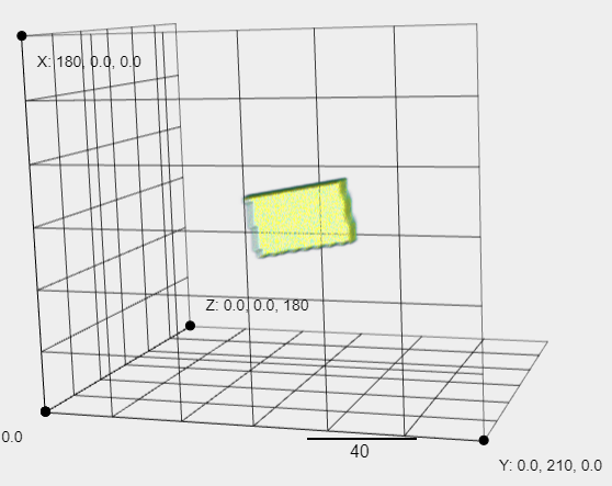
But if I first use the matrix of rotation around -x as my rotation matrix,
the result like below(Let’s call it “result\_x”)
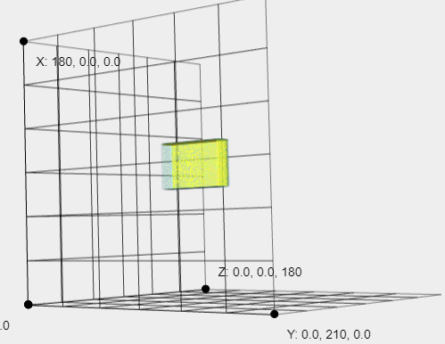
Then I use the matrix of rotation around y as my rotation matrix,
to rotation “result\_x”,the result like blow(Let’s call it “result\_x\_y”)
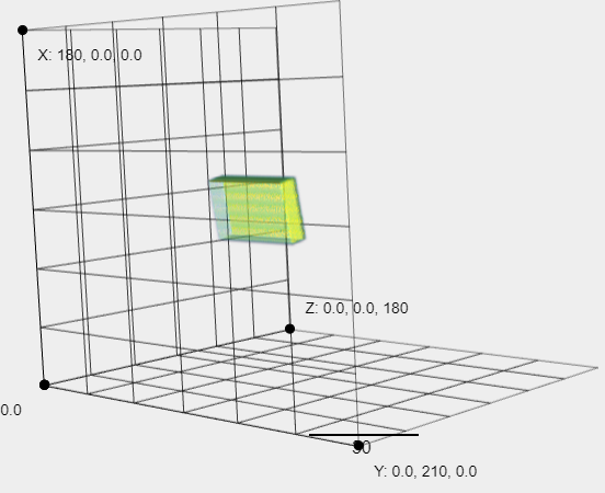
Why the result\_x\_y and the result\_XY are different?
---
### Author:  [@dzenanz](https://discourse.itk.org/u/dzenanz)
#### Post date: [September 19, 2022, 8:01pm UTC](https://discourse.itk.org/t/3d-affine-rotate-on-two-different-axes-one-after-the-other/5315/6 "2022-09-19T20:01:58Z")
The resulting compound rotation [depends on the order of single axis rotations](https://en.wikipedia.org/wiki/Euler_angles).
---
### Author:  [@wic94016](https://discourse.itk.org/u/wic94016)
#### Post date: [September 21, 2022, 8:43am UTC](https://discourse.itk.org/t/3d-affine-rotate-on-two-different-axes-one-after-the-other/5315/7 "2022-09-21T08:43:13Z")
Hi @dzenanz
May I ask how can I do external rotation in python with itk?
---
### Author:  [@dzenanz](https://discourse.itk.org/u/dzenanz)
#### Post date: [September 21, 2022, 12:11pm UTC](https://discourse.itk.org/t/3d-affine-rotate-on-two-different-axes-one-after-the-other/5315/8 "2022-09-21T12:11:09Z")
There are many [transform types in ITK](https://itk.org/Doxygen/html/group__ITKTransform.html). Find the simplest one which can do what you want, and use that.
You did not really explain what you want to accomplish. With rotations, it is usually easiest to compose transforms. Translate so the object is at the coordinate origin, rotate, then translate back. Otherwise the results are usually unintuitive.